Power-assisted braking system for a vehicle and method for controlling the power-assisted braking system

a technology of power-assisted braking and vehicle, which is applied in the direction of braking system, vehicle components, transportation and packaging, etc., to achieve the effect of cost-effective and compa

Inactive Publication Date: 2016-11-29
ROBERT BOSCH GMBH
View PDF22 Cites 0 Cited by
  • Summary
  • Abstract
  • Description
  • Claims
  • Application Information

AI Technical Summary

Benefits of technology

[0006]An example power-assisted braking system in accordance with the present invention may offer the advantage that a low-pressure accumulator is provided which stores hydraulic fluid under pressure, and supplies it to the actuator for activating the piston of the brake master cylinder. Such a low-pressure accumulator is relatively cost-effective and compact. The low-pressure accumulator supports the pump and the drive device driving it, in particular at times when the first pump is still unable to pump hydraulic fluid, since the inertia of the drive device has not yet been overcome.

Problems solved by technology

The low-pressure accumulator supports the pump and the drive device driving it, in particular at times when the first pump is still unable to pump hydraulic fluid, since the inertia of the drive device has not yet been overcome.

Method used


Image

  • Power-assisted braking system for a vehicle and method for controlling the power-assisted braking system
  • Power-assisted braking system for a vehicle and method for controlling the power-assisted braking system

Examples


Embodiment Construction

[0010]In the FIGURE, the same reference numerals denote the same elements or elements having the same function, unless otherwise indicated.

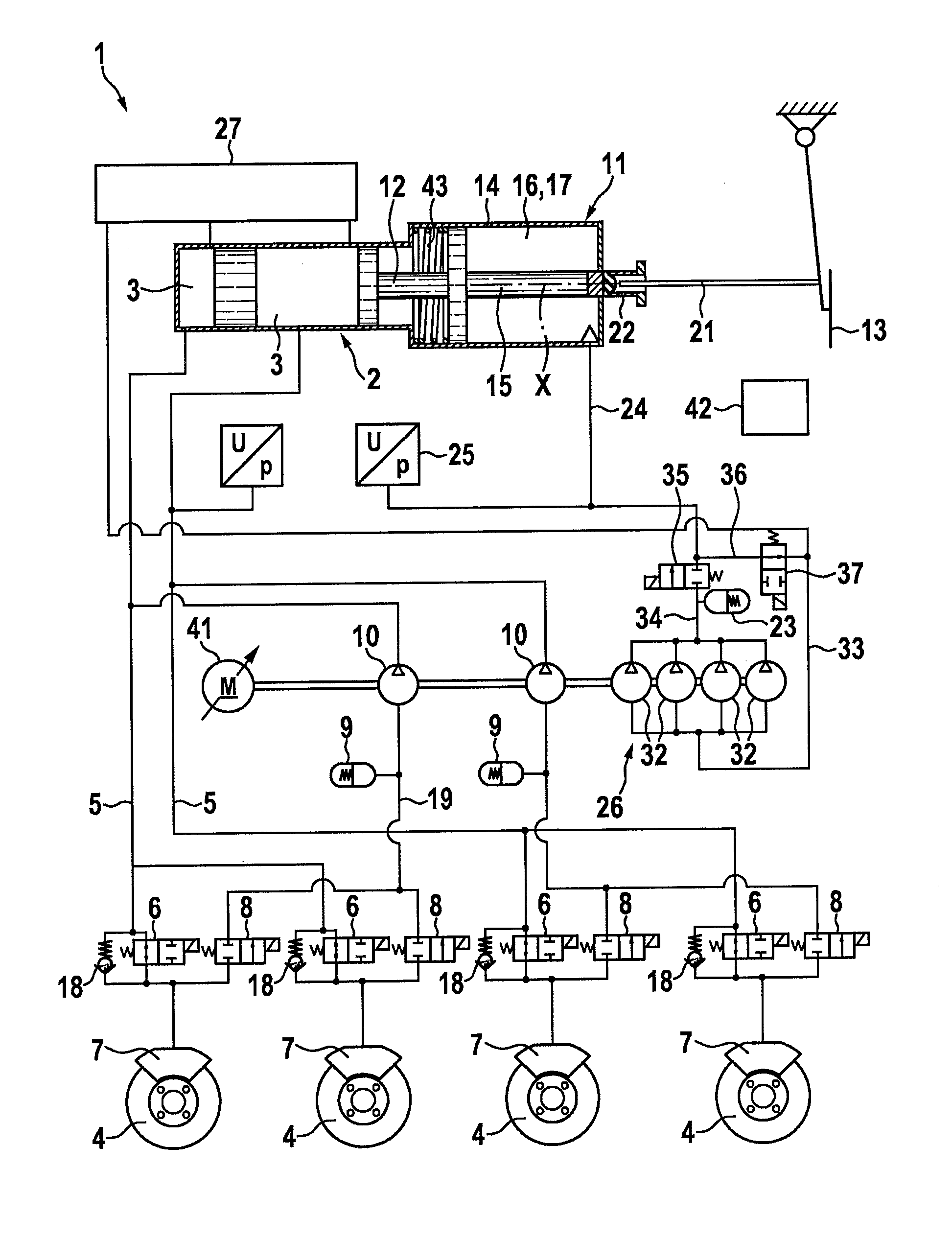
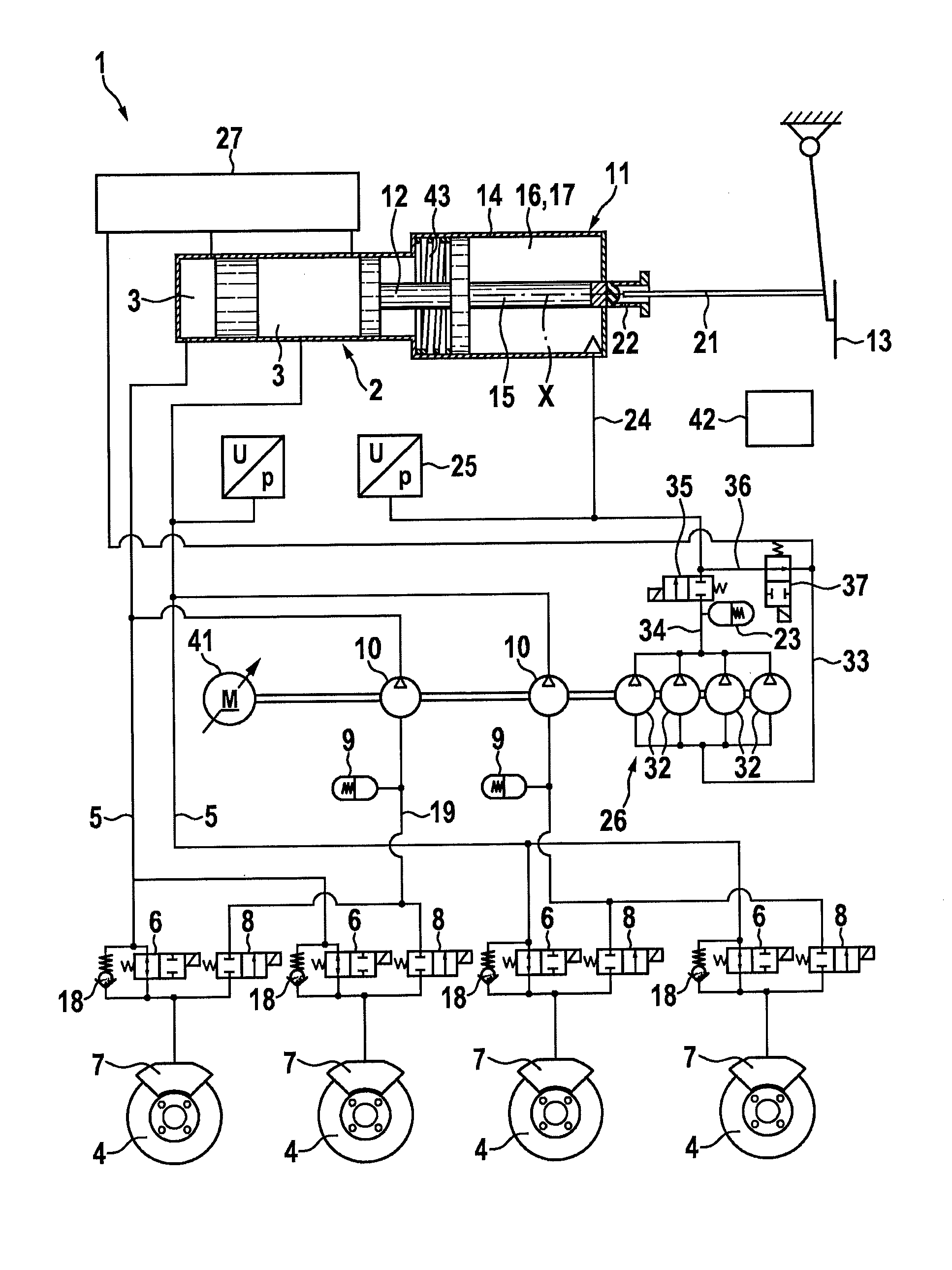
[0011]The FIGURE schematically shows a power-assisted braking system 1 according to one exemplary embodiment of the present invention.

[0012]Braking system 1 is preferably used in a motor vehicle not illustrated in detail.

[0013]Braking system 1 has a brake master cylinder 2 having two chambers 3, each of which is hydraulically connected to two wheel brake cylinders 7 with the aid of lines 5 for braking wheels 4 of the motor vehicle. Brake master cylinder 2 is preferably a tandem master cylinder (TMC). Each of lines 5 is connected to a wheel brake cylinder 7 with the aid of an inlet valve 6. Inlet valves 6 may be designed as 2 / 2-way valves, which are normally open, as shown in the FIGURE. Furthermore, return valves 18 are provided in parallel to inlet valves 6. Each of lines 5 may be branched in order to supply two wheel brake cylinders 7 with hydr...


PUM


Abstract

A power-assisted braking system for a vehicle is described, including: a brake master cylinder having a chamber which is hydraulically connected to a wheel brake cylinder for braking a wheel of the vehicle; a hydraulic actuator which activates a piston of the brake master cylinder in order to pressurize the hydraulic fluid in the chamber; a low-pressure accumulator which stores the hydraulic fluid under pressure, and the actuator for activating the piston of the brake master cylinder; a pump which supplies the hydraulic fluid from the tank to the low-pressure accumulator; and a drive device which drives the pump. A method for controlling a power-assisted braking system is also described.

Description

FIELD[0001]The present invention relates a braking system for a vehicle.BACKGROUND INFORMATION[0002]In braking systems for vehicles, a distinction is basically made between so-called power braking systems and power-assisted braking systems.[0003]In power braking systems, the brake master cylinder, which is hydraulically connected to the wheel brake cylinders, is operated using hydraulic fluid for acting on the wheel brake cylinders without direct transfer of the driver's foot power to the brake master cylinder. Such a power braking system is described, for example, in German Patent Application No. DE 10 2004 025 638 A1.[0004]In contrast, in power-assisted braking systems, a brake booster is used, which acts upon the brake master cylinder in addition to the driver's foot power for supplying hydraulic fluid to the wheel brake cylinders. Such a power-assisted braking system is described, for example, in German Patent No. DE 103 18 850 A1.[0005]A conventional power-assisted braking syst...

Claims


Application Information

Patent Timeline
Patent Type & Authority Patents(United States)
IPC IPC(8): B60T13/14B60T17/02B60T13/66B60T13/68B60T8/44B60T8/40
CPCB60T13/142B60T8/404B60T8/405B60T8/441B60T13/148B60T13/662B60T13/686B60T17/02B60T8/44B60T13/14
Inventor GERDES, MANFREDMAYER, JOCHEN
Owner ROBERT BOSCH GMBH
Why Eureka
Try Eureka