
Fishing rod with spiral fishing line guides

a fishing rod and spiral technology, applied in the field of fishing rod devices, can solve the problems of rod and line breakage, inaccurate casting, uneven weight distribution, etc., and achieve the effects of improving casting accuracy, enhancing fishing rod strength, and increasing durability

Inactive Publication Date: 2016-11-29
STENDER SCOTT
View PDF14 Cites 16 Cited by
  • Summary
  • Abstract
  • Description
  • Claims
  • Application Information

AI Technical Summary

Benefits of technology

The present invention is a new fishing rod that improves casting accuracy and strength while reducing fishing line breakages and tangling. The fishing line is guided in a gradual spiral around the fishing rod to prevent snagging or catching onto extraneous objects. The fishing line guides are low profile to prevent snagging and reduce or eliminate line memory. The new fishing rod also improves casting distance and accuracy.

Problems solved by technology

These devices, however, do not disclose a fishing rod with fishing line guides that are incrementally spaced in a spiral configuration around the length of the fishing rod, which improve the accuracy of the casts and increase the durability of the fishing rod.
The linear formation of the line guides results in dead weight hanging from the end of the fishing rod, which can cause the line to twist and tangle, leading to inaccurate casts, uneven weight distribution, and rod and line breakage.
As the devices disclosed in Tsurufuji, Yasui, and Roth are limited in the fact that the line guides are disposed in a linear formation along the fishing rod blanks, these prior art devices do not address the problem solved by the present invention.
The Sunaga device, however, is limited in the fact that the fishing line guides cannot be constructed in a spiral formation.
In this way, the Sunaga device is prone to rod breakage and inaccurate casts.

Method used


Image

  • Fishing rod with spiral fishing line guides
  • Fishing rod with spiral fishing line guides
  • Fishing rod with spiral fishing line guides

Examples


Embodiment Construction

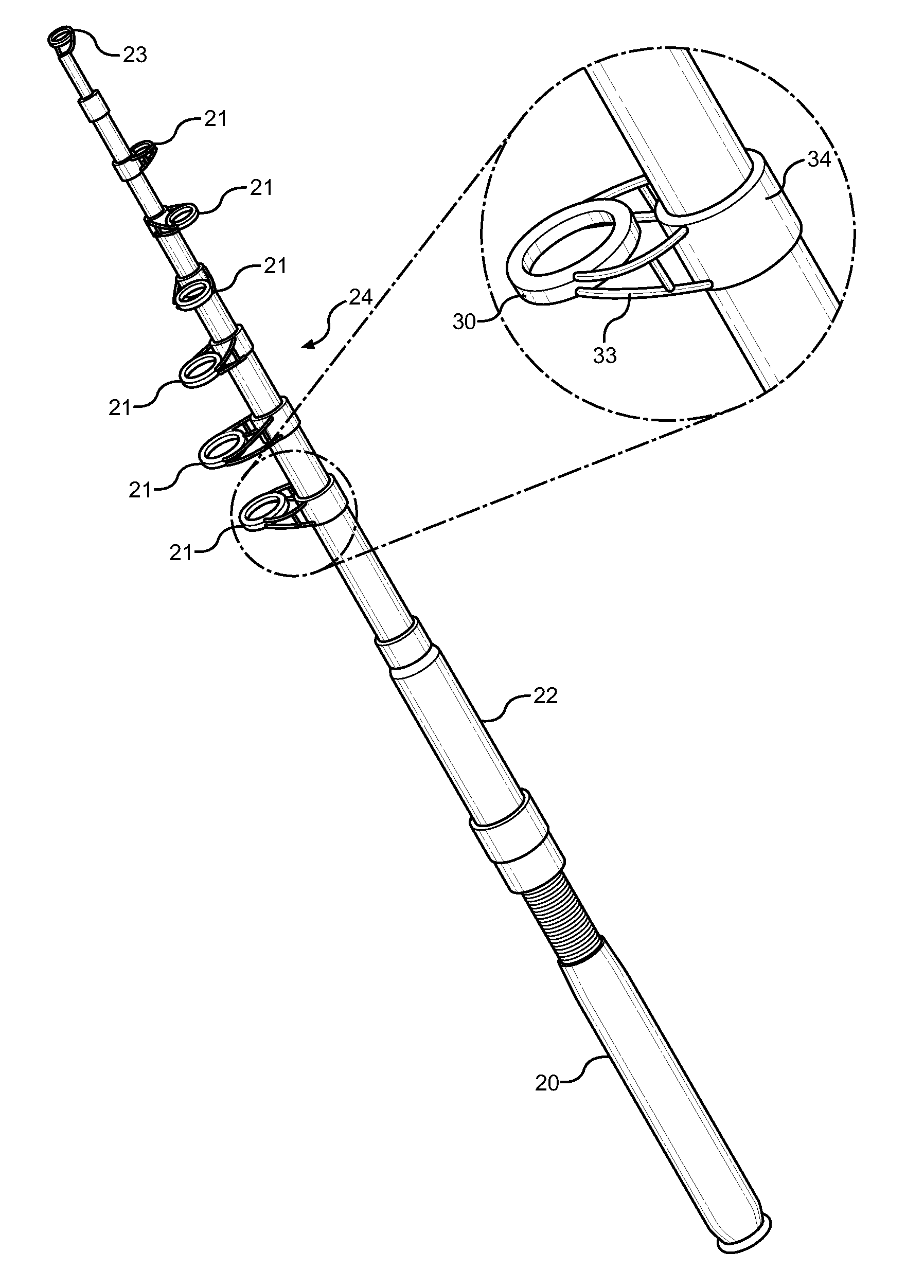
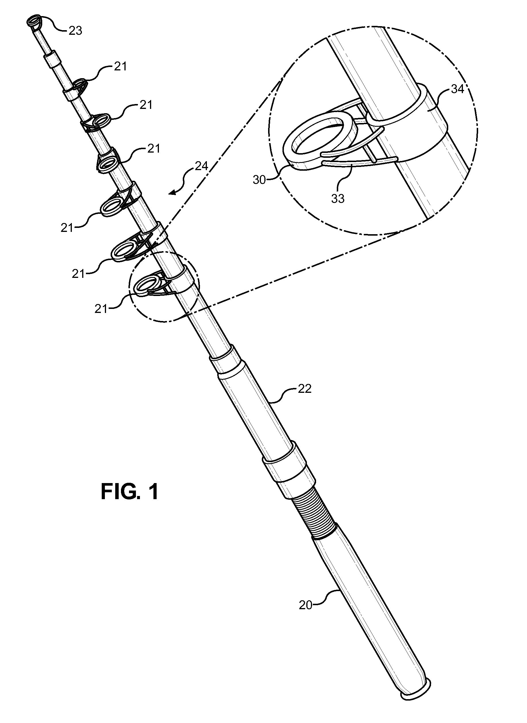
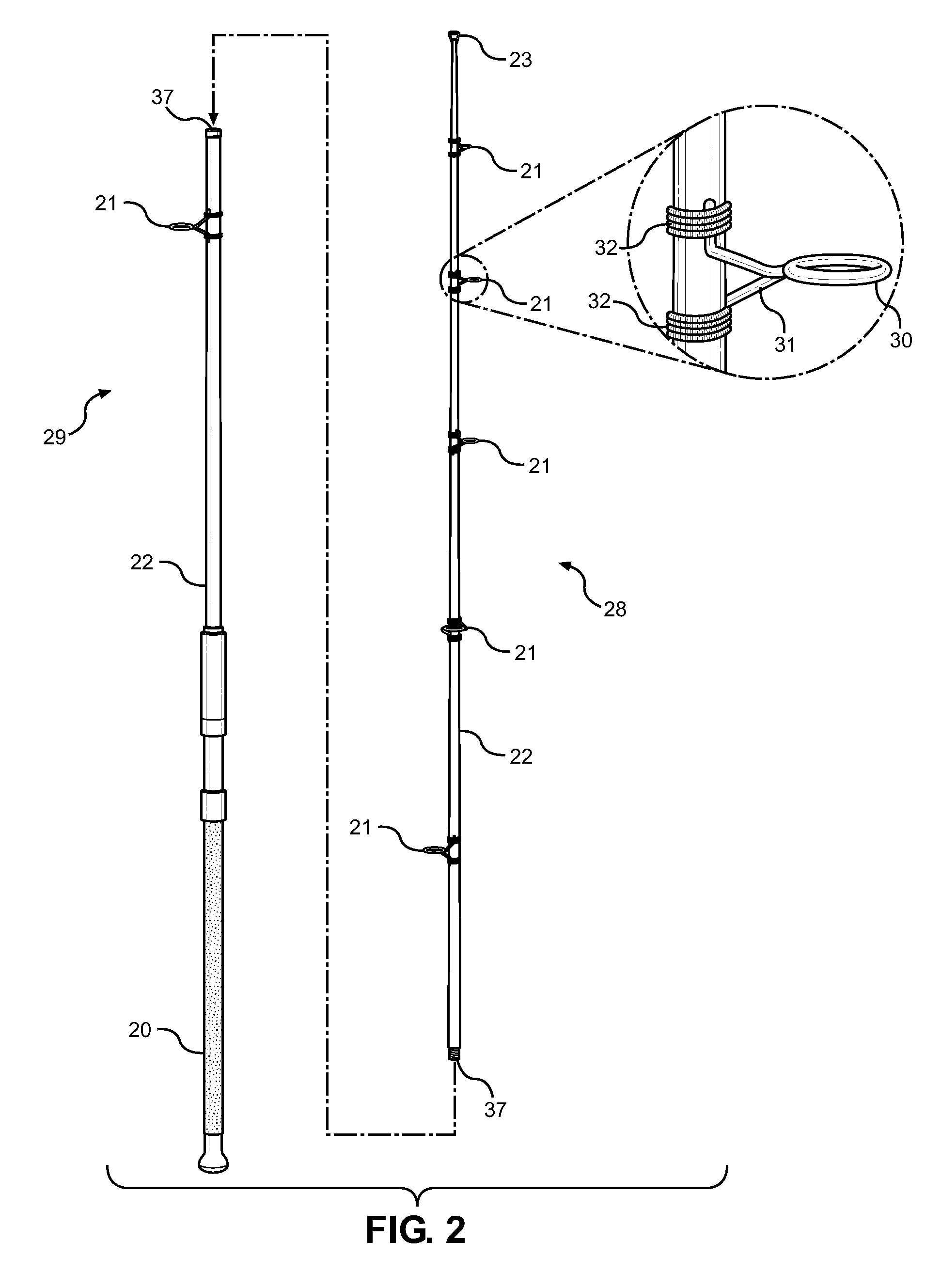
[0033]References is made herein to the attached drawings. Like reference numerals are used throughout the drawings to depict like or similar elements of the fishing rod device. For the purposes of presenting a brief and clear description of the present invention, the preferred embodiment will be discussed as used for increasing durability of the fishing rod and providing an improved casting distance and accuracy. The figures are intended for representative purposes only and should not be considered to be limiting in any respect.

[0034]Referring now to FIG. 1, there is shown a perspective view of the preferred embodiment of the fishing rod 24 of the present invention. The fishing rod 24 comprises an elongated rod blank 22, wherein the rod blank 22 comprises bamboo, graphite, fiberglass, composite, or other suitable material. The rod blank 22 is a tapered shaft having a circular cross section with a diameter that varies over the axial length of the rod blank 22. The fishing rod blank 2...


PUM


Abstract

Disclosed is an improved fishing rod adapted to increase the durability of the fishing rod and fishing line and to improve casting distance and accuracy. The fishing rod comprises an elongated cylindrical rod blank having a working end and a terminal end, wherein the working end is attached to a handle. The rod blank further comprises a plurality of fishing line guides disposed in a gradual spiral configuration along the length of the rod blank. The fishing line guides are adapted to receive a fishing line therethrough. The guides are also low profile so as to minimize snagging. When in use, the fishing line wraps around the rod blank, thereby evenly distributing the weight of the fishing line around the rod. In this way, the present invention eliminates line memory and increases the tensile strength of the rod blank and the fishing line.

Description

CROSS REFERENCE TO RELATED APPLICATION[0001]This application claims the benefit of U.S. Provisional Application No. 61 / 831,444 filed on Jun. 5, 2013. The above identified patent application is herein incorporated by reference in its entirety to provide continuity of disclosure.BACKGROUND OF THE INVENTION[0002]Field of the Invention[0003]The present invention relates to fishing rod devices. More specifically, the present invention pertains to an improved fishing rod that increases the tensile strength of the fishing rod blank and a fishing line, wherein the location of the fishing line guides are improved over existing fishing rod devices. The fishing rod of the present invention is designed for use with various types of fishing lines to accommodate different types of fishing, thereby providing versatility to the user with regards to the use of the device.[0004]Fishing is a popular recreational activity. The most common form of recreational fishing is done with a rod, reel, line, hoo...

Claims


Application Information

Patent Timeline
Patent Type & Authority Patents(United States)
IPC IPC(8): A01K87/04A01K87/02
CPCA01K87/04A01K87/025
Inventor STENDER, SCOTT
Owner STENDER SCOTT
Learn More