
Methods and systems for determining the positions of orthodontic appliances

a technology for orthodontic appliances and positions, applied in the field of methods and systems for determining the position of orthodontic appliances, can solve the problems of considerable care, difficulty in ensuring the practitioner, and process is somewhat time-consuming and difficult to carry out with precision, so as to achieve precise and repeatable results, the effect of quick and accurate defining the marginal ridge height of the patient's teeth, and difficult and time-consuming determination

Active Publication Date: 2016-11-22
3M INNOVATIVE PROPERTIES CO
View PDF26 Cites 8 Cited by
  • Summary
  • Abstract
  • Description
  • Claims
  • Application Information

AI Technical Summary

Benefits of technology

The patent describes a system that uses software and a digital data file to accurately determine the need for adjusting the placement of appliances in orthodontic treatment. This saves time and reduces the risk of inaccurate results using manual techniques, which can result in a more efficient and effective treatment plan.

Problems solved by technology

As another example, if the bracket is placed to one side of the center of the tooth in either the mesial or distal direction, the resultant tooth orientation will likely be an orientation that is excessively rotated about its long axis.
The process of positioning and bonding the appliances to the patient's teeth requires considerable care, and the practitioner often must visually determine the proper location of the brackets on the respective teeth.
However, this process is somewhat time-consuming and difficult to carry out with precision, and may be subjective in nature.
Consequently, it is often difficult for the practitioner to ensure that the brackets are precisely positioned on the teeth at correct locations.

Method used


Image

  • Methods and systems for determining the positions of orthodontic appliances
  • Methods and systems for determining the positions of orthodontic appliances
  • Methods and systems for determining the positions of orthodontic appliances

Examples


Embodiment Construction

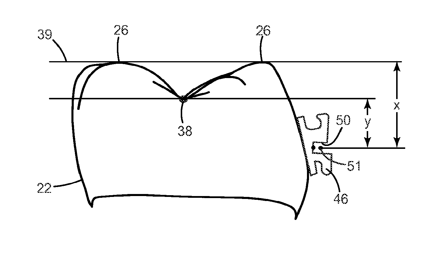
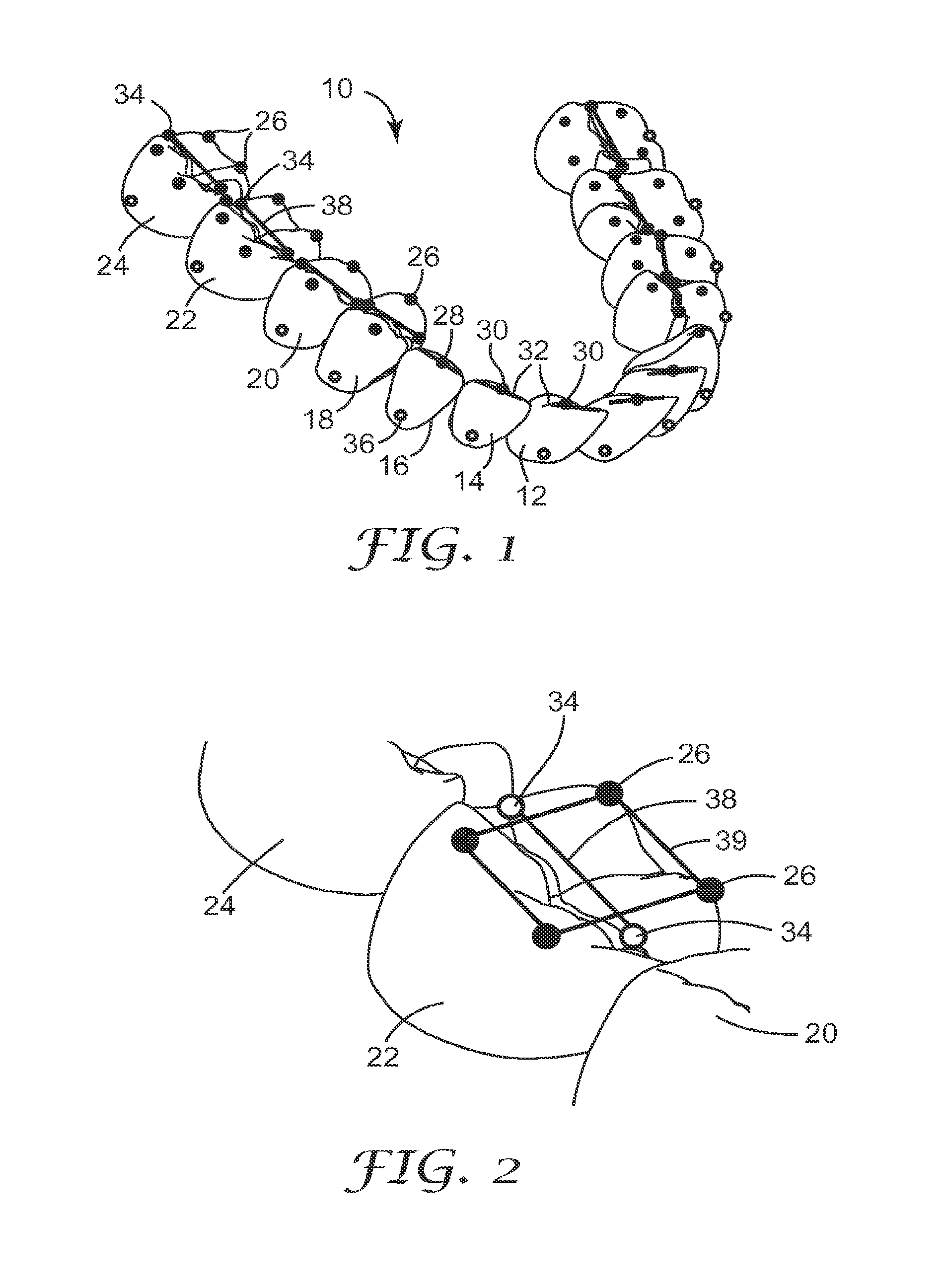
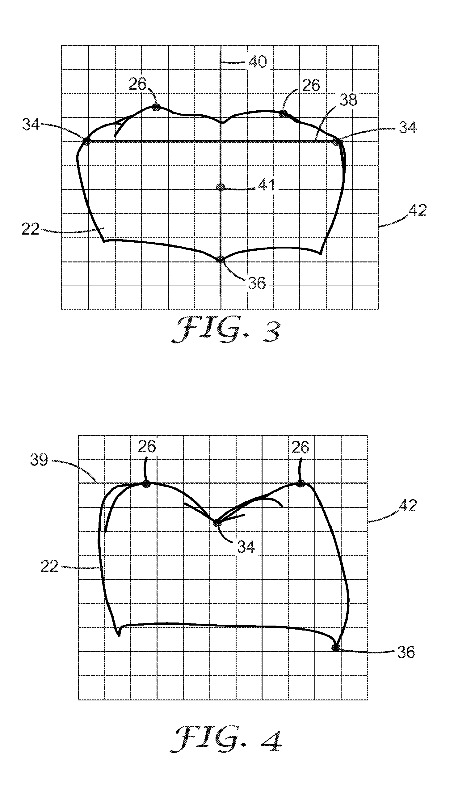
[0030]A method of determining the position of orthodontic appliances according to one embodiment of the invention includes the act of obtaining a digital data file that is representative of the shapes of teeth of a dental arch. The data file may be obtained, for example, through the use of a scanning device such as an intra-oral camera that is held in the patient's oral cavity or by the use of X-ray apparatus or other type of radiation apparatus. Alternatively, the digital data file may be obtained through use of a contact probe that engages the surfaces of the patient's teeth at a multitude of locations.

[0031]As another alternative, the digital data file representative of the shapes of teeth of the dental arch may be obtained by first taking an impression of the patient's teeth using a curable impression material. Next, a data file is obtained by scanning the impression with a camera or other device or by scanning a physical model that is made from the impression. As yet another op...


PUM


Abstract

The positions of orthodontic appliances such as brackets and buccal tubes on a patient's teeth are determined using digital data that represents the shapes of the patient's teeth. Certain landmarks of the teeth such as the marginal ridges are determined using software, and the software adjusts positions of the virtual appliances on the teeth as needed in order to bring the marginal ridges into proper alignment at the conclusion of treatment. The resulting positions are optionally used to determine the location of the appliances in an indirect bonding apparatus such as a transfer tray.

Description

CROSS REFERENCE TO RELATED APPLICATIONS[0001]This application is a national stage filing under 35 U.S.C. 371 of PCT / US2009 / 056299, filed Sep. 9, 2009, which claims priority to U.S. Application No. 61 / 098,336, filed Sep. 19, 2008, the disclosure of which is incorporated by reference in its / their entirety herein.BACKGROUND OF THE INVENTION[0002]1. Field of the Invention[0003]This invention relates to methods and systems for determining positions of a number of orthodontic appliances on respective teeth of a patient's dental arch.[0004]2. Description of the Related Art[0005]The field of orthodontics is concerned with repositioning and aligning a patient's teeth for improved occlusion and aesthetic appearance. Orthodontic treatment often involves the use of tiny slotted appliances known as brackets that are fixed to the patient's anterior, canine, and bicuspid teeth. An archwire is received in the slot of each bracket and serves as a track to guide movement of the teeth to desired orien...

Claims


Application Information

Patent Timeline
Patent Type & Authority Patents(United States)
IPC IPC(8): A61C7/14H04L12/58H04N1/00
CPCH04L12/5835H04L51/066H04N1/00212H04N1/00214H04N1/00217H04N1/00312H04N1/00281H04N2201/0094A61C7/002A61C7/146H04L51/08H04N1/0022H04N1/00244H04L51/48
Inventor KODY, ROBERT S.KUHNS, DAVID W.RABY, RICHARD E.
Owner 3M INNOVATIVE PROPERTIES CO
Learn More