Cable retraction unit assembly

Active Publication Date: 2016-11-22
KUM OH ELECTRONICS
View PDF27 Cites 15 Cited by
  • Summary
  • Abstract
  • Description
  • Claims
  • Application Information

AI Technical Summary

Benefits of technology

This patent describes a cable retraction unit assembly that allows a mobile device to be easily handled and manipulated without resistance or breaking of the cable. The assembly includes a guide housing and withdrawal guide mounted to a table, with the cable penetrating through them. A guide unit is rotatably provided within the guide housing, so that the cable can rotate smoothly without twisting or breaking. The guide unit also includes a locking unit and ball bearings for easy handling of the mobile device. Additionally, at least one of the guide unit and the withdrawal guide is provided with a roller to prevent breaking of the cable during retraction and extension. The guide housing and withdrawal guide can be coupled by adjusting the length of the locking bolt, making it easier to couple regardless of the table's thickness.

Problems solved by technology

However, the burglar alarm device and cable for displaying goods is problematic in that it is impossible to extend or to arrange the cable between the attachment unit for attaching a product thereto and a control unit, thereby causing inconvenience to a user who wishes to examine the demonstrated product.
However, the conventional art is problematic in that when the earphones are extended from the housing, a first cable and a second cable, which are connected to the housing, may twist or be broken.
However, the earphone integrated type portable terminal case is problematic in that rotations by the multiple rotation connection terminals must still allow electrical connection, whereby a structure is complicated and it is difficult to electrically connect the terminals when not in place.
However, the apparatus for arranging a cable is problematic in that the apparatus is for winding and arranging one cable, and is configured such that the main body is disposed in the middle of the cable, whereby when the cable is extended, the main body is located in the middle of the cable, causing inconvenience.

Method used


Image

  • Cable retraction unit assembly
  • Cable retraction unit assembly
  • Cable retraction unit assembly

Examples


Embodiment Construction

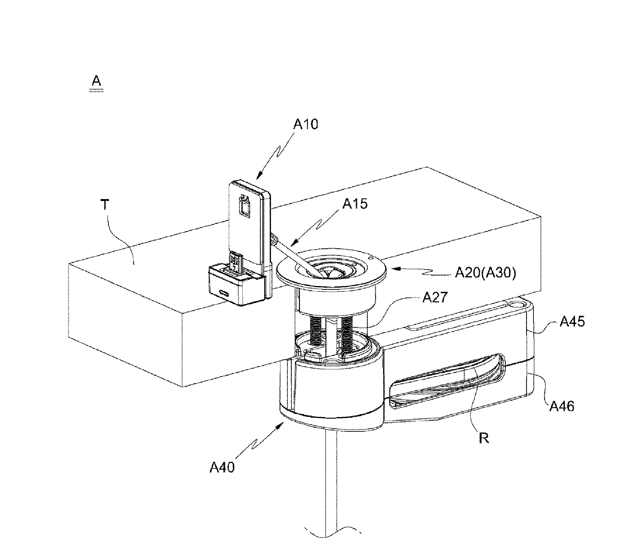
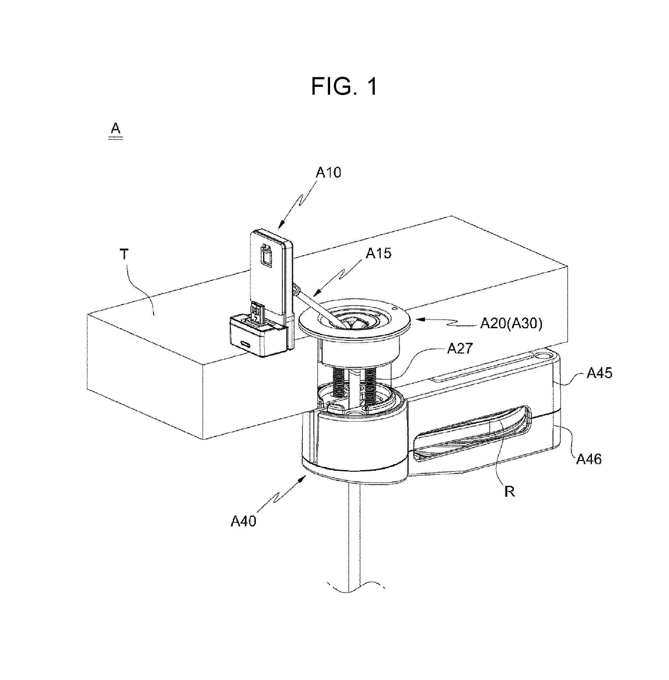
[0041]Hereinbelow, exemplary embodiments of the present invention will be described in detail with reference to the accompanying drawings.

[0042]The present invention will now be described in detail based on aspects (or embodiments). The present invention may, however, be embodied in many different forms and should not be construed as being limited to only the embodiments set forth herein, but should be construed as covering modifications, equivalents or alternatives falling within ideas and technical scopes of the present invention.

[0043]In the figures, like reference numerals, particularly, tens and units, or reference numerals having like tens, units and letters refer to like elements having like functions throughout, and unless the context clearly indicates otherwise, elements referred to by reference numerals of the drawings should be understood based on this standard.

[0044]Also, for convenience of understanding the elements, in the figures, sizes or thicknesses may be exaggerat...


PUM


Abstract

Provided is a cable retraction unit assembly connected to a table for displaying a mobile device. The cable retraction unit assembly includes: a cable connected to a mobile device; a guide housing and a withdrawal unit respectively mounted to an upper portion and a lower portion of a table, with the cable penetrating through the guide housing and the withdrawal unit; and a guide unit rotatably provided within the guide housing, wherein the guide unit is configured to rotate in response to a rotating direction of the cable when the cable rotates, thereby being capable of preventing twisting or breaking of the cable.

Description

CROSS REFERENCE TO RELATED APPLICATION[0001]The present application claims priority to Korean Patent Application No. 10-2015-0086452, filed Jun. 18, 2015, the entire contents of which is incorporated herein for all purposes by this reference.BACKGROUND OF THE INVENTION[0002]Field of the Invention[0003]The present invention relates generally to a cable retraction unit assembly that is connected to a table for displaying a mobile device. More particularly, the present invention relates to a cable retraction unit assembly including: a cable connected to a mobile device; a guide housing and a withdrawal unit respectively mounted to an upper portion and a lower portion of a tabletop, with the cable penetrating through the guide housing and the withdrawal unit; and a guide unit rotatably provided within the guide housing, wherein the guide unit is configured to rotate in response to a rotating direction of the cable when the cable rotates, thereby being capable of preventing twisting or b...

Claims


Application Information

Patent Timeline
IPC IPC(8): B65H75/00B65H75/44
CPCB65H75/4402B65H75/4471B65H75/4428B65H2701/3919A47F7/024G08B13/1409G08B13/1463H01R13/72H02G11/02H02G3/185H01R12/775
Inventor KIM, KI SANG
Owner KUM OH ELECTRONICS
Why Eureka
Try Eureka