
Determining well integrity

a well integrity and well technology, applied in the field of determining well integrity, can solve the problems of casing collapse, fluid displacement and/or expansion in the annulus, and the integrity of the well can be affected

Active Publication Date: 2016-11-15
LANDMARK GRAPHICS CORP +1
View PDF16 Cites 5 Cited by
  • Summary
  • Abstract
  • Description
  • Claims
  • Application Information

AI Technical Summary

Benefits of technology

[0017]In one or more specific aspects of the general embodiment, the method may further include providing at least one of a maximum burst pressure value of one casing string in between two annuli; a maximum collapse pressure value of the one casing string in between the two annuli; and a value of an annular fluid expansion in one of the two annuli.
[0035]In one or more specific aspects of the general embodiment, the operations may further include providing: a maximum burst pressure value of one casing string in between two annuli; a maximum collapse pressure value of the one casing string in between the two annuli; and a value of an annular fluid expansion in one of the two annuli.
[0083]In a eighteenth aspect according any of the preceding aspects, the well integrity tool may further perform operations including: providing a maximum collapse pressure value of the one casing string in between the two annuli.

Problems solved by technology

Under operation, the well experiences varying temperatures and pressures, which can cause increased stresses on the components and may cause displacement and / or expansion of fluids in the annulus between components.
Because of such change in loading conditions to the well, the well integrity can be affected.
For example, some common well integrity issues include casing collapse, casing burst, and liftoff from the wellhead, among others.
Well integrity may be even more difficult to determine in subsea wells, because the wellhead is not readily accessible or capable of being easily monitored (e.g., for fluid leakages and other indications of well integrity problems).

Method used


Image

  • Determining well integrity
  • Determining well integrity
  • Determining well integrity

Examples


Embodiment Construction

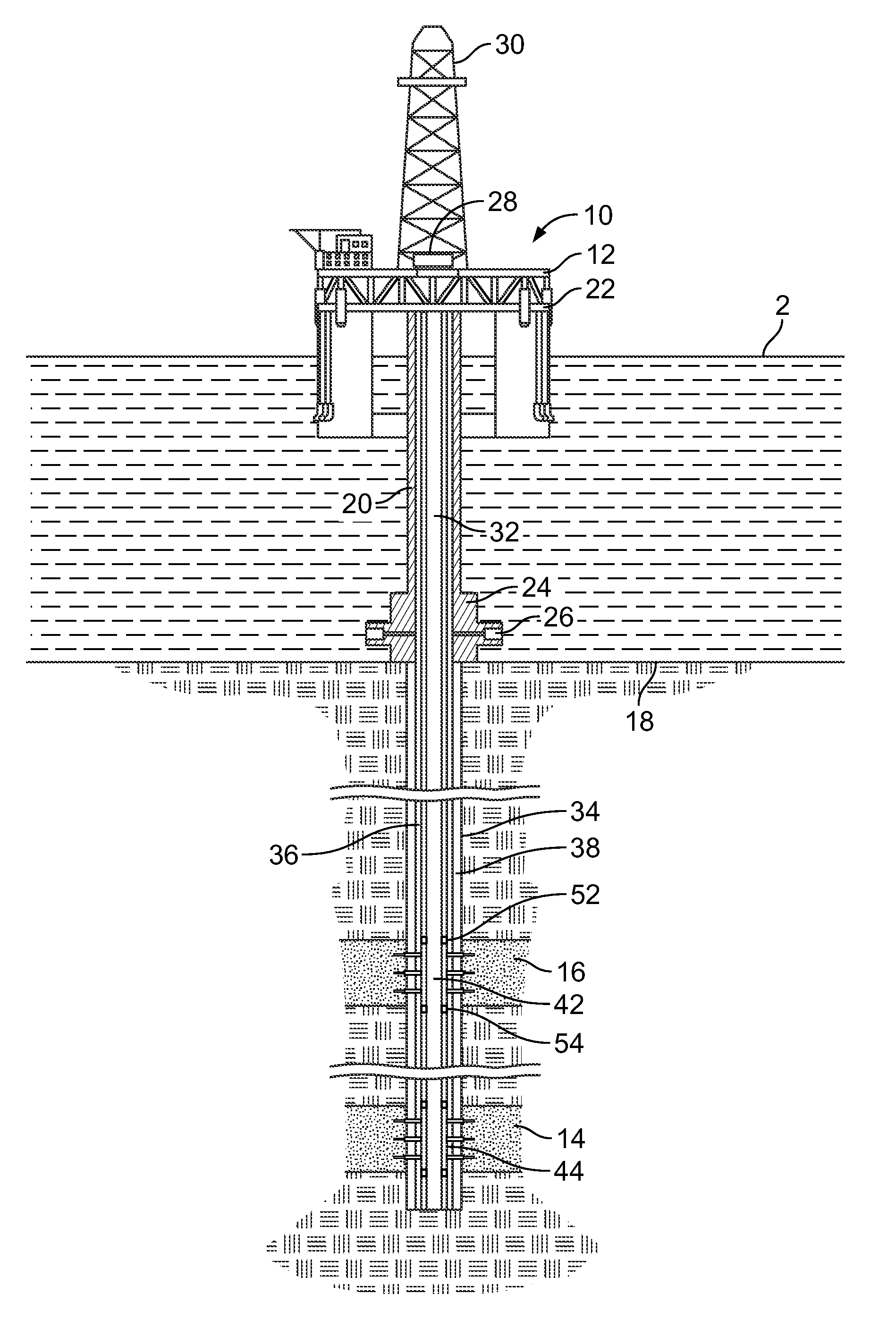
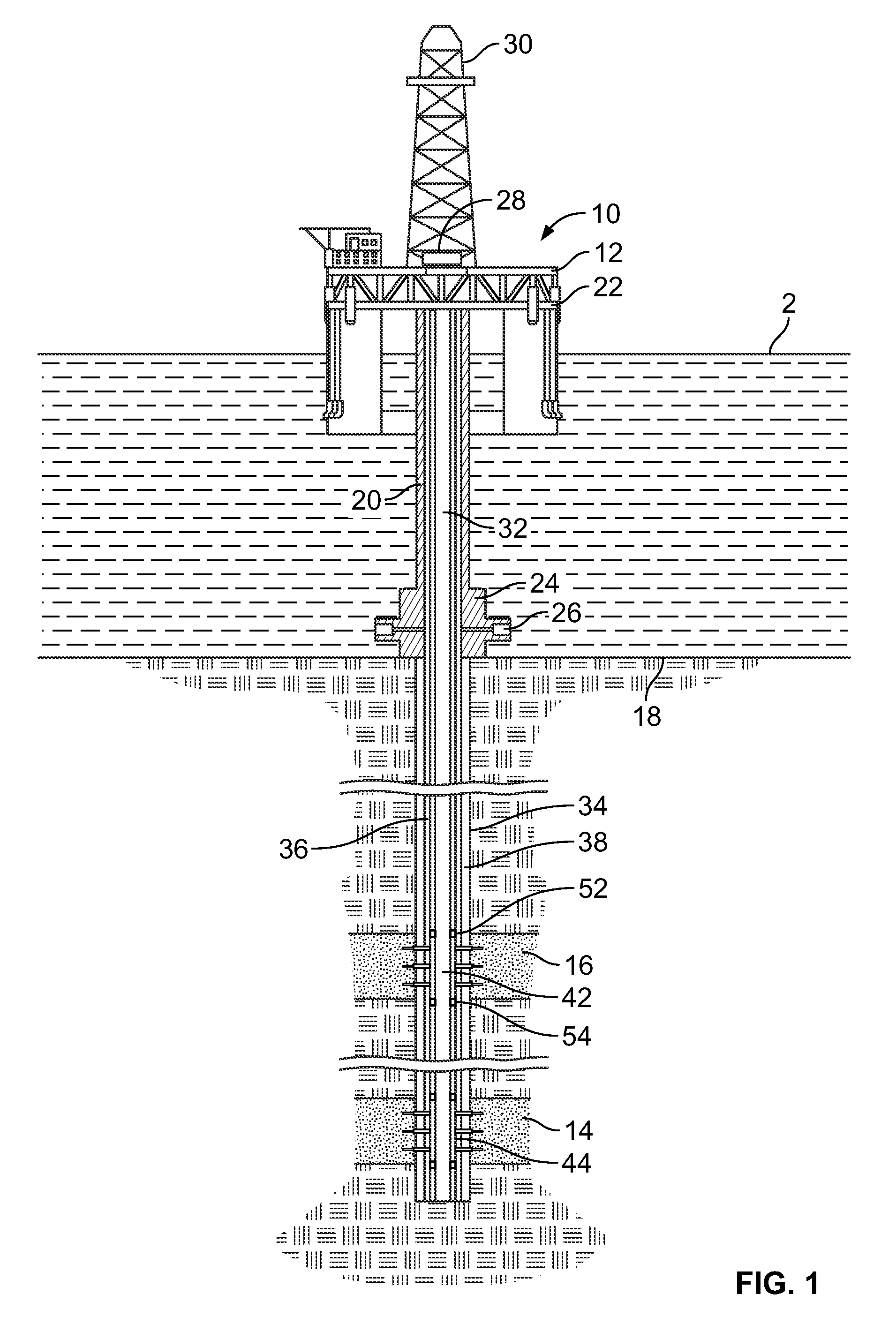
[0009]In some embodiments, a well integrity tool implemented on a computation device determines and / or predicts well integrity of a well configuration (e.g., a proposed well configuration or a constructed (all or partially) well). The well integrity tool can analyze, compute, optimize, determine and predict critical values or properties of the well integrity, therefore aiding well design / planning and preventing various failure modes. Complex well loading conditions can be evaluated with this disclosure. Well design engineers can plan ahead against conventional well loading conditions that could become critical, as well as complex well loading conditions that could be detrimental to the well integrity, safety and the environment.

[0010]One or more embodiments of a well integrity tool according to the present disclosure may include one or more of the following features. For example, the well integrity tool may use temperature and pressure information to accurately calculate the loading...


PUM


Abstract

A method performed with a computing system for determining well integrity includes receiving a selection of a well configuration of a well, and receiving a selection of a wellbore operation performed with the well configuration. The selected well configuration includes one or more casing strings and a production tubing extending from adjacent a wellhead of the well to adjacent a bottom of the well. In some examples, the method further includes determining, based on the well configuration and the wellbore operation, a characteristic of the well at or adjacent the one or more casing strings and the production tubing during the wellbore operation, and modifying the well configuration to remove the production tubing. In some examples, the method still further includes determining, based on the modified well configuration and the wellbore operation, the characteristic of the well at or adjacent the one or more casing strings during the wellbore operation.

Description

TECHNICAL BACKGROUND[0001]This disclosure relates to determining well integrity in, for example, subsea, deepwater environments.BACKGROUND[0002]Technical, operational and organizational solutions can be applied to reduce risk of uncontrolled release of formation fluids throughout the life cycle of a well. One of the solutions is to use computer software to relatively accurately model (detection, optimization, prediction, or otherwise.) well construction and operation. A production well usually includes liners, casing (head, spools and hangers), cement, annulus between casings, tubing (head and hanger), packoff seals, test plugs, bowl protectors, and mudline suspension systems, and other components. Under operation, the well experiences varying temperatures and pressures, which can cause increased stresses on the components and may cause displacement and / or expansion of fluids in the annulus between components. Because of such change in loading conditions to the well, the well integr...

Claims


Application Information

Patent Timeline
Patent Type & Authority Patents(United States)
IPC IPC(8): G01V99/00E21B47/00
CPCG01V99/005E21B47/00E21B2200/20
Inventor GONZALES, ADOLFOMITCHELL, ROBERT
Owner LANDMARK GRAPHICS CORP
Learn More