
Method for manufacturing the impeller of a centrifugal compressor

Active Publication Date: 2016-11-15
RUNTECH SYST
View PDF61 Cites 3 Cited by
  • Summary
  • Abstract
  • Description
  • Claims
  • Application Information

AI Technical Summary

Benefits of technology

The present invention improves the efficiency of composite construction by utilizing a manufacturing method that optimizes material usage. This approach allows for the production of impellers for blowers and compressors without the limitations of prior art methods. The use of a composite material impeller allows for simultaneous optimization of the entire machinery functions. The invention utilizes a RTM process to manufacture the impeller, which results in a more complicated and technically demanding structure than prior art methods. The method offers a shorter work cycle, inasmuch no time is lost in postprocessing. The invention provides significant advantages, including improved utilization of composite construction.

Problems solved by technology

As the fabrication of such a construction from sheet elements is impractical, casting is typically employed as the manufacturing method.
However, the rotational speed of such a compressor is not adjustable inasmuch as the control range would extend to the critical speed that could cause damage to the machinery.
However, direct mounting on the motor shaft poses certain technical constraints.
Yet, there is a limit to the use of a thick shaft, because the diameter of bearings also increases.
Another factor affecting the critical speed is the mass of the impeller.
Components manufactured from prepreg materials are quite expensive due to the great number of work hours and costly raw materials.
Manufacture of impellers by way of this approach is highly labor intensive, because the preparation of a thick laminate structure requires plural intermediate vacuum pumping cycles.
Machining is labor-intensive and cuts fibers.
Particularly problematic are severed fibers at the leading edge of the impeller vane that meets the gas flowing at a high velocity, whereby it must be noted that the flow frequently carries along a certain amount of particulates.
However, the weakest point in a structure assembled from separate elements is always the bonded seam.
Both prior-art manufacturing methods described above are highly labor-intensive.
Moreover, certain other problems have occurred in practical applications.
In comparison with metallic impellers, all carbon-fiber composite structures are generally hampered by inferior endurance under erosive conditions.
Solid particulates impinging on the composite structure cause abrasive wear that eventually deteriorates the impeller.
In practice, the above-described embodiments have been problematic.
Particularly due to differences in thermal expansion coefficients, high rotational speed and the like reasons, the shields / guards have separated under use thereby causing serious damage.
It must further be noted that prepreg materials also impose constraints to the product geometry, since the prepreg itself as well as the core material are rather sheet-like thus being incompatible with the lamination 3D structures.
Resultingly, prior-art embodiments have been hampered by plural disadvantages that have retarded actual advancements in the development of composite material impellers.

Method used


Image

  • Method for manufacturing the impeller of a centrifugal compressor
  • Method for manufacturing the impeller of a centrifugal compressor
  • Method for manufacturing the impeller of a centrifugal compressor

Examples


Embodiment Construction

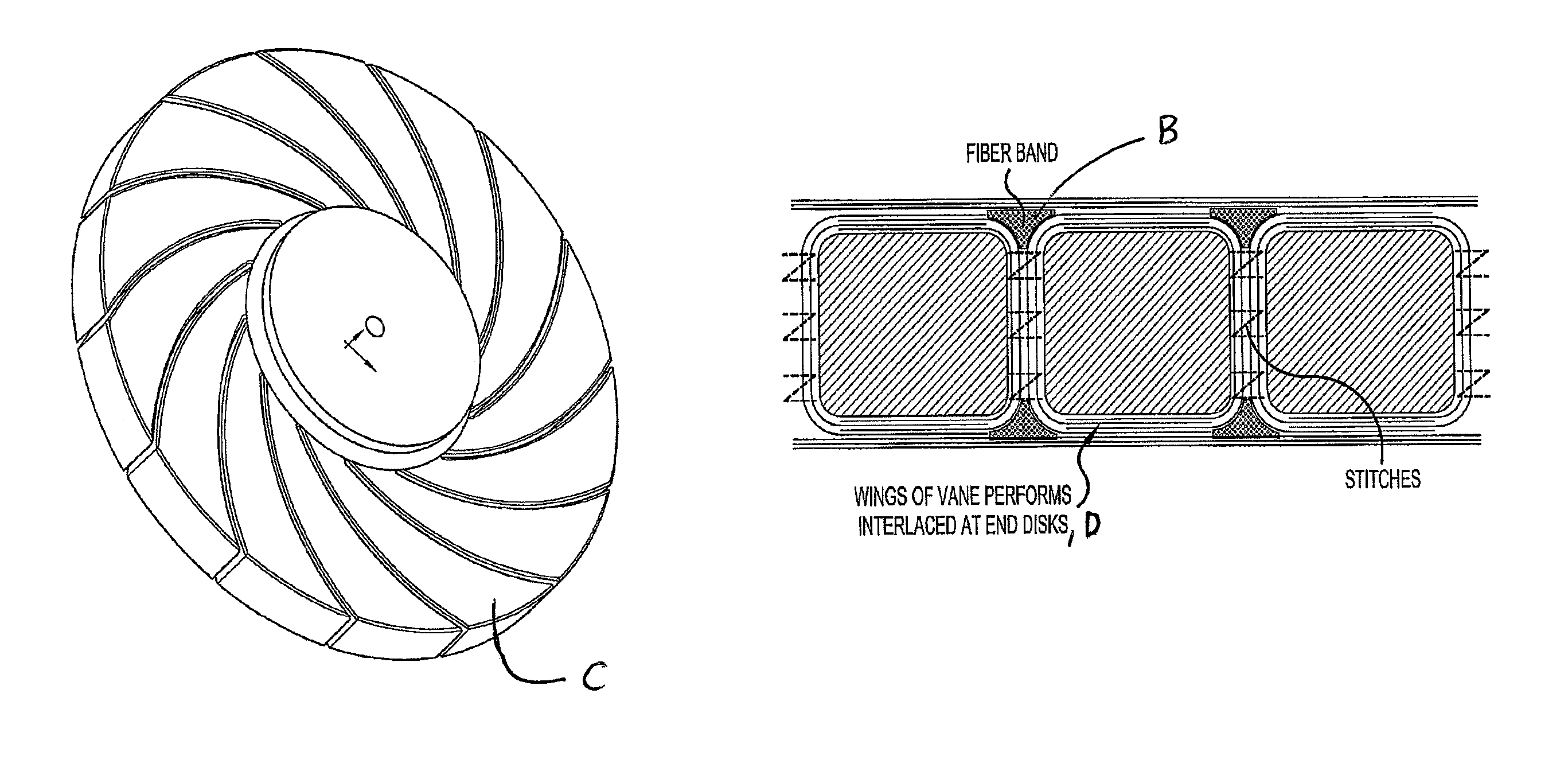
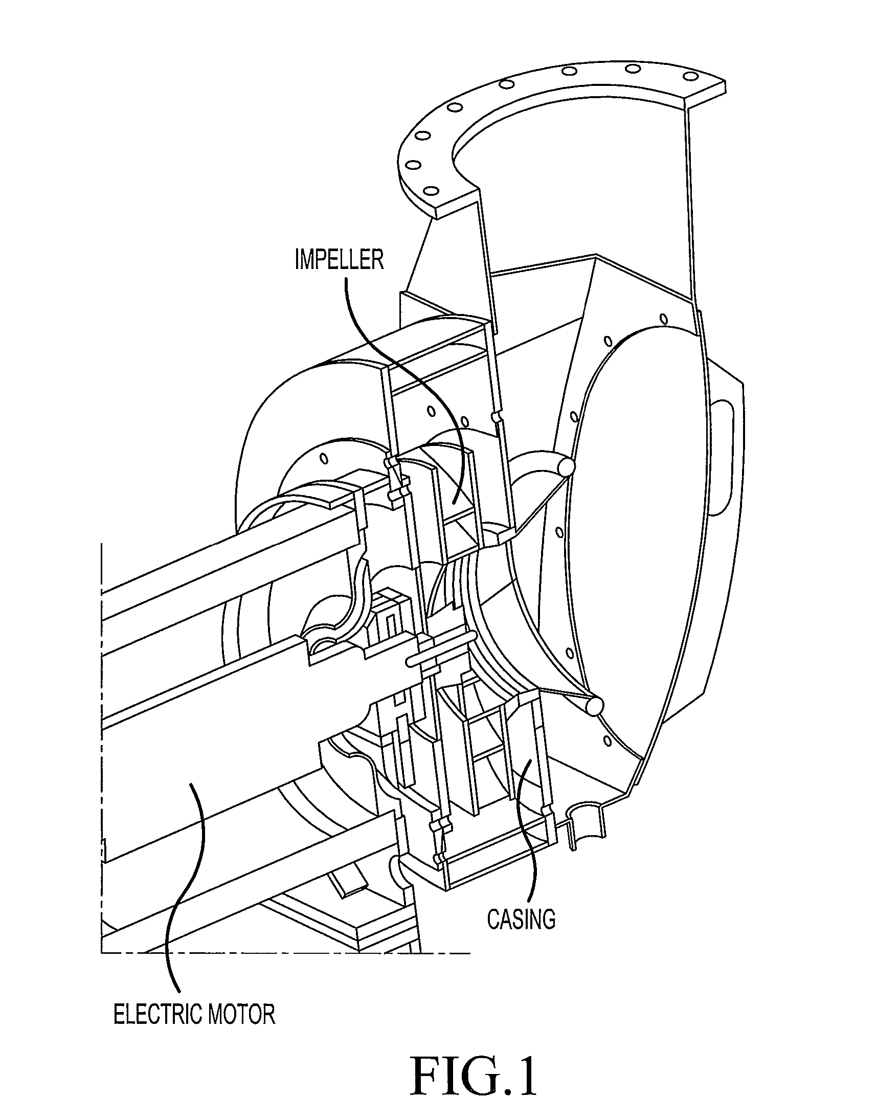
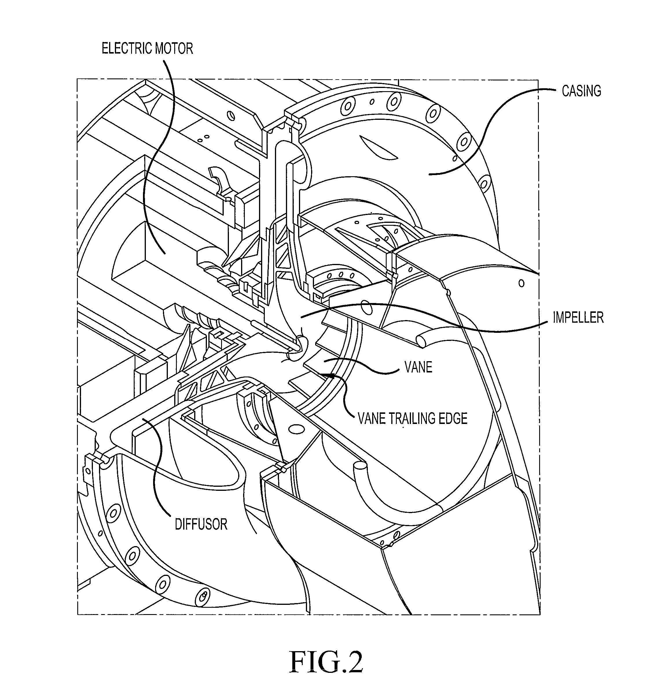
[0030]FIGS. 1 and 2 show the basic components of a typical compressor. As illustrated in FIG. 1, the construction of a compressor or blower comprises an impeller serving to accelerate a gas flow by centrifugal force and a spiral-shaped flow-controlling structure called casing. In the sectional view of FIG. 2, the construction is implemented in a compressor construction mounted directly on the shaft of an electric motor in a basic manner employed in the structure described in the present invention. According to the method of the present invention, as illustrated in FIG. 3, the process comprises preparation of a first breakable / meltable / dissolvable core C as well as a second core deformable by vacuum / pressure of compressed air or liquid, the latter core delineating the flow paths of the impeller. In the art is known a plurality of alternative materials suited for use in the manufacture of hollow-core products. According to the invention, all the fabric layers of the vanes V and disks ...


PUM

PropertyMeasurementUnit
Thicknessaaaaaaaaaa

Abstract

The invention relates to a method for manufacturing the impeller of a centrifugal, that is, a radial compressor or radial blower, said impeller being mounted directly on the shaft of an electric motor. An essential feature of the invention is that the composite material impeller is made using an RTM process, wherein the RTM mold has a core and accurately trimmed fabrics placed therein in such a manner that the fabric layers, or preforms, are pulled onto the core thus achieving a maximally optimized use of materials in the structure.

Description

CROSS-REFERENCE TO RELATED APPLICATION[0001]The present application claims priority under 35 U.S.C. §119 to Finnish Patent Application No. 2010-284060, filed Jan. 21, 2010, the entire contents of which are hereby incorporated by reference.BACKGROUND OF THE INVENTION[0002]1. Field of the Invention[0003]The invention relates to a method for manufacturing the impeller that is capable of being mounted on a shaft of an electric motor of a radial compressor or radial blower, and the use of the same.[0004]2. Description of the Background Art[0005]In the prior art, a great number of different types of compressors and blowers are known being used in various applications. Particularly in industrial applications, pumping of gases is accomplished with the help of centrifugal compressors, also known as radial compressors, and radial blowers. Typically this kind of blower construction comprises a rotary impeller, such as shown in FIG. 1, serving to accelerate the gas flow by centrifugal force, an...

Claims


Application Information

Patent Timeline
IPC IPC(8): B23P15/04B29C70/02B29C70/48B29C70/54F04D29/02F04D29/28B29C33/44B29C33/52
CPCB29C70/025B29C70/48B29C70/543F04D29/023F04D29/281F04D29/284B29C33/448B29C33/52F05D2260/95F05D2300/603Y10T29/49329F04D25/06F04D29/2227
Inventor KARVINEN, JUHA
Owner RUNTECH SYST
Learn More