Tube support for vibration mitigation

a technology of supporting devices and tubes, applied in the direction of stationary tubular conduit assemblies, indirect heat exchangers, lighting and heating apparatus, etc., can solve the problems of tube failure, tube vibration, and unstable eddies, and achieve the effect of less vibration and more rigidity

Active Publication Date: 2016-11-08
WANNI AMAR SIRI
View PDF16 Cites 8 Cited by
  • Summary
  • Abstract
  • Description
  • Claims
  • Application Information

AI Technical Summary

Benefits of technology

[0017]The tube stake that is essential to my invention has at least one protrusion formed along its length, the protrusion having a forward end and a rearward end. The elongated stake is inserted in a tube lane so that a first tube is located at the forward end of the protrusion and a second, next adjacent tube of the bundle is positioned at the rearward end of the protrusion. The protrusion is sized so that, in tube contacting position, it exerts a force on the tubes that at least has a component that is substantially parallel to the longitudinal axis of the stake, so that the opposed faces move the contacted tubes away from each other and stress the tubes. In this manner the tubes are made more rigid and their vibration during the flow of fluid across them is reduced.

Problems solved by technology

Such a crosswise flow tends to create unstable eddies on the downstream side of some or all tubes.
Under some conditions, such eddies may lead to vibration of the tubes.
Depending on the intensity of these vibrations, some tubes may experience excessive displacements from their original (i.e., with no flow condition) locations and eventually lead to tube failures.
Tube damage owing to flow-induced vibration can occur very quickly (several days or weeks) or take several years.
Also, a properly designed exchanger may experience such failures owing to a recent increase in shellside flow rate, the flow conditions, tube wall corrosion, etc.
Tube failures often require isolation of the exchanger for repair thereby causing costly downtime (e.g., production losses) and the associated repair costs as well as operational risks.
While the technologies presented by Wanni, et al. solve most of the problems they had described, the new technologies proposed by Wanni, et al. also have several limitations.
First, the dimples located on one end of the tube support as well as the protrusions along the remaining length require substantial amount of metal deforming (starting from a flat thin strip of metal), especially, for the rectangular tube arrangement which has the widest tube lanes.
As a result, proper forming of dimples would be difficult for harder metallurgies, such as Titanium and Duplex Steel, where penetrating cracks are difficult to avoid.
Second, fabrication of tube support requires a very high pressing force (in excess of 200 tons representing expensive machinery), especially, when a single pressing operation is used.
The use of multiple pressings along the length of the tube support decreases the required pressing force, but this lowers the technical quality of the stake and also increases the production time substantially.
Third, fabrication of these tube supports requires the use of high-precision die sets that are very expensive and they will wear out and can be damaged with repeated use.
Fourth, these tube supports cannot properly support those tubes that are located very close to the shell inner diameter when U-tube bundles are involved; this is because some of the tubes can be located only ⅛″ (3.2 mm) away from the shell inner diameter, but the dimples have a thickness of ⅜″ (9.5 mm) in this region.
Fifth, the dimples at the outer end of the tube support do not provide an adequately robust locking with the nearby tubes so that the stake can pivot around this outer end and rotate under some conditions, especially when the tube support has a somewhat loose fit within the tube bundle.
Sixth, the equipment used for the purpose of fabricating the tube supports with the dimples and protrusions does not lend itself easily to achieve an adjustable overall thickness for the tube support.
Seventh, once the tube support is formed, its overall thickness, that determines the extent of vibration mitigation, cannot be adjusted in any way.
This could lead to inadequate tube support in certain regions of a tube bundle or additional tube support must be used to achieve an acceptable level of vibration mitigation.

Method used


Image

  • Tube support for vibration mitigation
  • Tube support for vibration mitigation
  • Tube support for vibration mitigation

Examples


Embodiment Construction

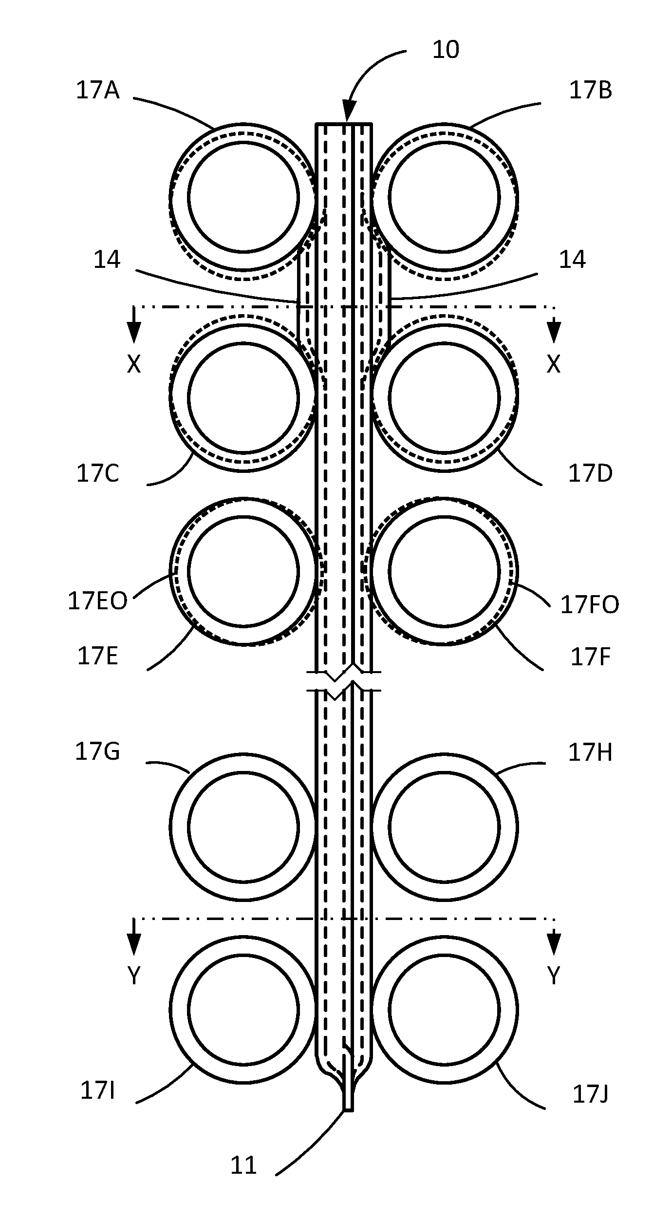
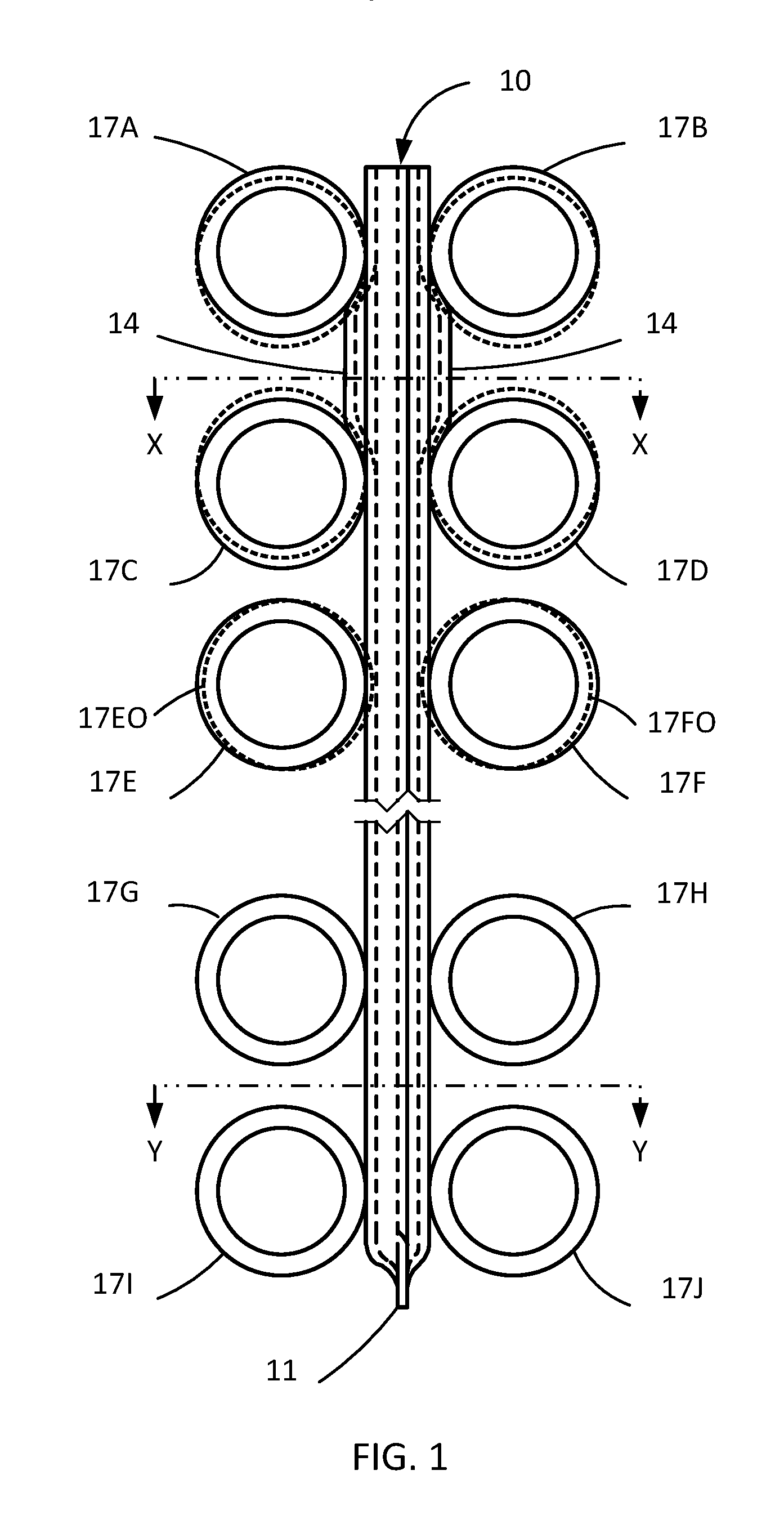
[0032]The tube support or stake device of the present invention provides direct and robust support to the tubes on both sides flanking the stake. In its preferred embodiment the stake has an effective thickness that is greater than the spacing between the tubes to account for the clearance between the tubes and the holes in the baffles as well as to account for the slight warping of the tubes.

[0033]The length of the stake may be selected to satisfy the number of tubes requiring such support based on the estimated vibration damage potential. In fact, in some regions, such support may be needed across the entire tube bundle while some other regions may require support only to a depth of several tube rows. If necessary, the stake may extend across the entire bundle cross-section, but insertion of the stake would be somewhat easier if the stake length is limited to a maximum equal to the bundle radius.

[0034]Since the stake deflects all of the tubes that it comes in contact with, for the...


PUM


Abstract

A tube support in the form of a stake having at least one protrusion mounted on its longitudinal surface. The protrusion contacts adjoining tubes of a tube bundle and exerts a force tending to separate the tubes.

Description

FIELD OF THE INVENTION[0001]This invention relates to tube support devices, which are also called tube stakes that are inserted into tube bundles in heat exchangers and other fluid-handling equipment.BACKGROUND OF THE INVENTION[0002]Heat exchangers and other fluid-handling equipment are often fitted with tube bundles that are fabricated by the attachment of a collection of tubes to one or two tubesheets. The tubes in the bundle may be arranged in two primary layouts: rectangular (also referred to as inline arrangement) and triangular (also referred to as staggered arrangement). The rectangular arrangement leads to tubes that are aligned vertically and horizontally while the triangular arrangement sets three adjacent tubes at the vertices of an equilateral triangle.[0003]The tube bundle may be fitted with a series of baffles that provides support to the tubes while also diverting the shellside flow across the tube bundle in a serpentine manner. The firm attachment of tubes to the tub...

Claims


Application Information

Patent Timeline
Patent Type & Authority Patents(United States)
IPC IPC(8): F28F9/013F28D7/06
CPCF28F9/013F28D7/06F28F9/0132
Inventor WANNI, AMAR SIRI
Owner WANNI AMAR SIRI
Why Eureka
Try Eureka