
Method and system to enable selective smoke detection sensitivity

a smoke detection and sensitivity technology, applied in the direction of aircraft fire/erosion prevention, fire alarm smoke/gas actuation, instruments, etc., can solve the problems of low likelihood of false alarm, low risk of false alarm, and low desire for early detection, etc., to achieve selective smoke detection sensitivity

Active Publication Date: 2016-10-18
THE BOEING CO
View PDF6 Cites 7 Cited by
  • Summary
  • Abstract
  • Description
  • Claims
  • Application Information

AI Technical Summary

Benefits of technology

This solution allows for tailored smoke detection sensitivity, reducing false alarms and enabling earlier detection of smoke or fire, particularly when carrying low-risk cargo, thereby enhancing safety and operational efficiency.

Problems solved by technology

With such known smoke detection methods and systems, when smoke in an area of an aircraft becomes sufficiently dense, it will typically trigger the smoke detection system and cause an alarm in the flight deck signaling the presence of a fire.
However, known smoke detection methods and systems may typically have only one alarm setpoint.
This false alarm tolerant system assumes certain types of cargo (e.g., fresh flowers, fish) may accidentally trigger a false alarm, if fog from moisture, dust, or other false alarm nuisances, are present.
For example, when carrying batteries, such as lithium batteries, as cargo, the likelihood of a false alarm may be low, while the desire for an early detection may be high.
In many cases, inert cargo, such as packages, machinery, batteries, and the like, may be carried but may pose a low risk of causing a false alarm.
In these cases, smoke detection methods and systems may be unnecessarily “desensitized” for false alarm immunity.
In addition, with known smoke detection methods and systems, it may be difficult, without installing new smoke detectors altogether, for flight crews to change or vary the smoke detector sensitivity in order to increase the smoke detector sensitivity in the aircraft.

Method used


Image

  • Method and system to enable selective smoke detection sensitivity
  • Method and system to enable selective smoke detection sensitivity
  • Method and system to enable selective smoke detection sensitivity

Examples


Embodiment Construction

[0029]Disclosed embodiments will now be described more fully hereinafter with reference to the accompanying drawings, in which some, but not all of the disclosed embodiments are shown. Indeed, several different embodiments may be provided and should not be construed as limited to the embodiments set forth herein. Rather, these embodiments are provided so that this disclosure will be thorough and fully convey the scope of the disclosure to those skilled in the art.

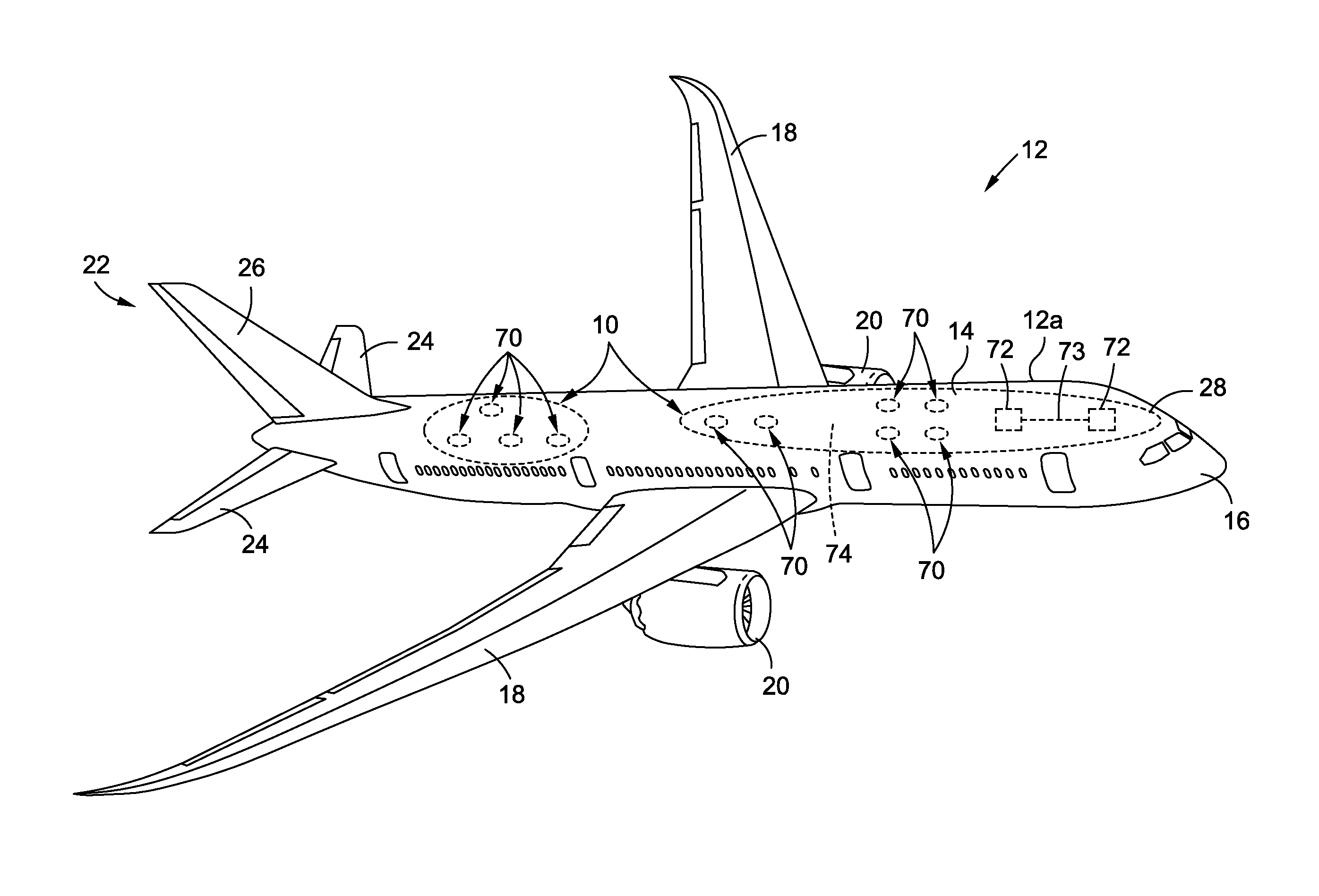
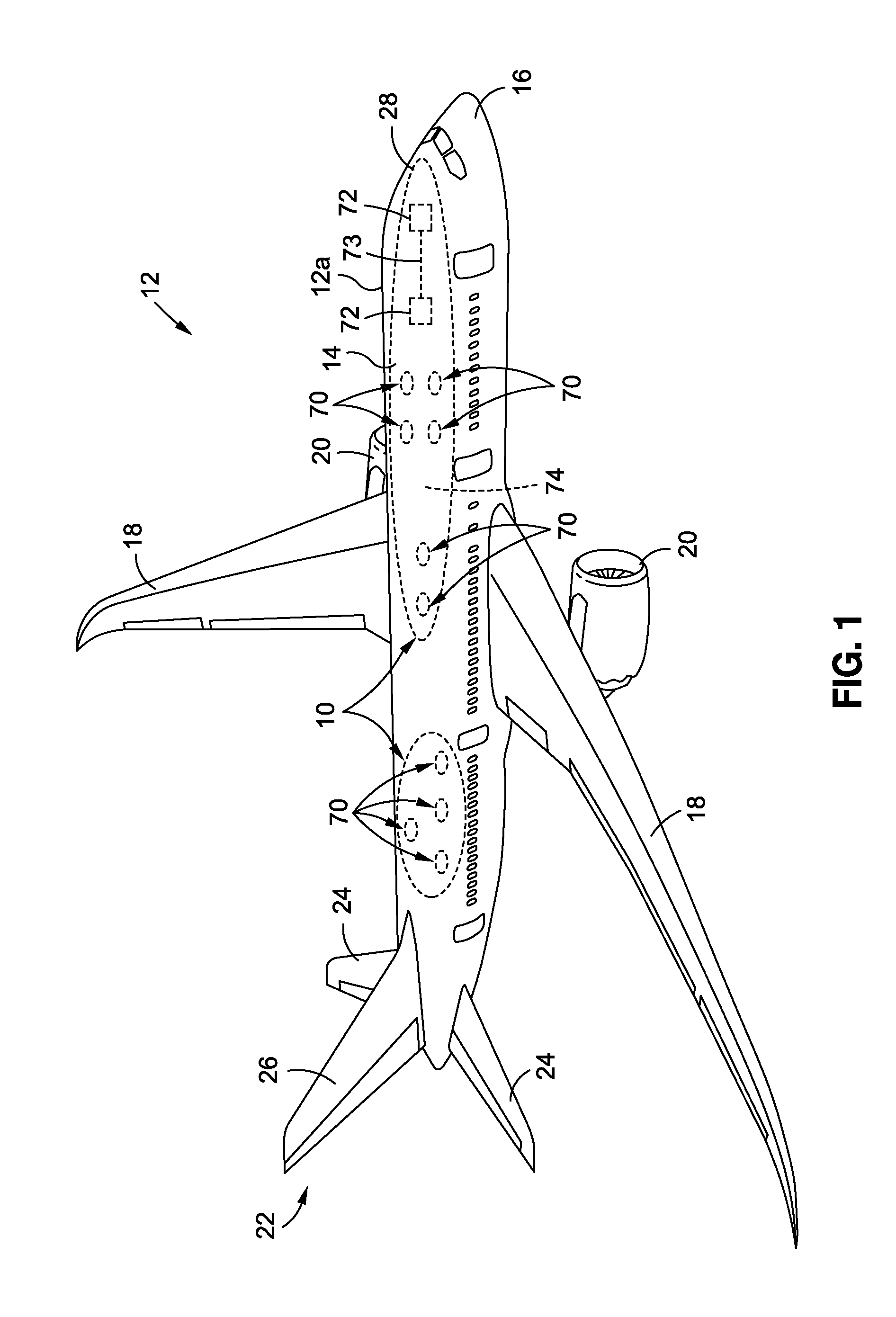
[0030]Now referring to the Figures, FIG. 1 is an illustration of a perspective view of an air vehicle 12, such as in the form of an aircraft 12a, that may incorporate one or more embodiments of a system 10 (see FIGS. 4A-4B, 8), a method 200 (see FIG. 6), or a method 300 (see FIG. 7) of the disclosure to enable selective smoke detection sensitivity onboard the air vehicle 12, such as in the form of aircraft 12a.

[0031]As further shown in FIG. 1, the air vehicle 12, such as in the form of aircraft 12a, comprises a fuselage 14...


PUM


Abstract

There is provided a method to enable selective smoke detection sensitivity onboard an aircraft. The method has the step of installing one or more sensitivity selectable smoke detector assemblies. The method further has the step of electrically or wirelessly coupling the one or more sensitivity selectable smoke detector assemblies installed onboard the aircraft to one or more sensitivity selector controls installed onboard the aircraft. The method further has the step of selecting an alarm setpoint sensitivity level from two or more alarm setpoint sensitivity levels for each of the one or more sensitivity selectable smoke detector assemblies, based on sensitivity level determination factors of one or more of a mission type of the aircraft, a cargo type on the aircraft, a compartment zone specific area type on the aircraft, and an occupancy state on the aircraft.

Description

BACKGROUND[0001]1) Field of the Disclosure[0002]The disclosure relates generally to smoke detection systems and methods, and more particularly, to selective smoke detection sensitivity systems and methods for air vehicles, such as commercial passenger aircraft and cargo aircraft.[0003]2) Description of Related Art[0004]Known methods and systems exist for smoke detection on air vehicles, such as commercial passenger aircraft and cargo aircraft. With such known smoke detection methods and systems, when smoke in an area of an aircraft becomes sufficiently dense, it will typically trigger the smoke detection system and cause an alarm in the flight deck signaling the presence of a fire. Smoke detection system sensitivity is a key factor in how long it takes to detect smoke / fire. The faster smoke or fire is detected, the faster a flight crew can initiate fire suppression systems and divert the air vehicle to an airport.[0005]However, known smoke detection methods and systems may typically...

Claims


Application Information

Patent Timeline
Patent Type & Authority Patents(United States)
IPC IPC(8): G08B23/00G08B17/10
CPCG08B17/10B64D45/00B64D2045/009G08B29/22
Inventor MEIER, OLIVER C.
Owner THE BOEING CO
Learn More