
Preparation of thin layers of a fluid containing cells for analysis

a technology of fluid and cells, applied in the field of apparatus and methods for preparing thin layers of fluid for analysis, can solve problems such as inability to use processes, and achieve the effect of increasing the angle count and being very stabl

Active Publication Date: 2016-10-18
KONINK PHILIPS ELECTRONICS NV
View PDF23 Cites 23 Cited by
  • Summary
  • Abstract
  • Description
  • Claims
  • Application Information

AI Technical Summary

Benefits of technology

This approach enables fast, reproducible, and precise creation of monolayers of red blood cells with controlled layer thickness, reducing false positives / negatives in imaging-based diagnostics by ensuring uniform analysis across large areas and preventing white blood cell obstruction.

Problems solved by technology

For an integrated closed cartridge this process cannot be used.

Method used


Image

  • Preparation of thin layers of a fluid containing cells for analysis
  • Preparation of thin layers of a fluid containing cells for analysis
  • Preparation of thin layers of a fluid containing cells for analysis

Examples


first embodiment

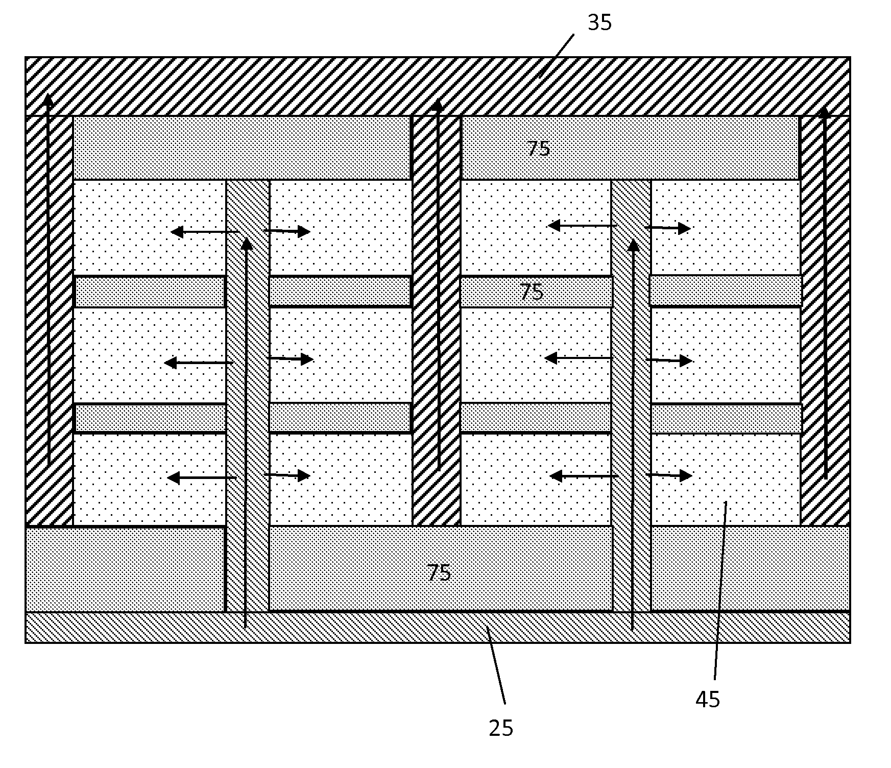
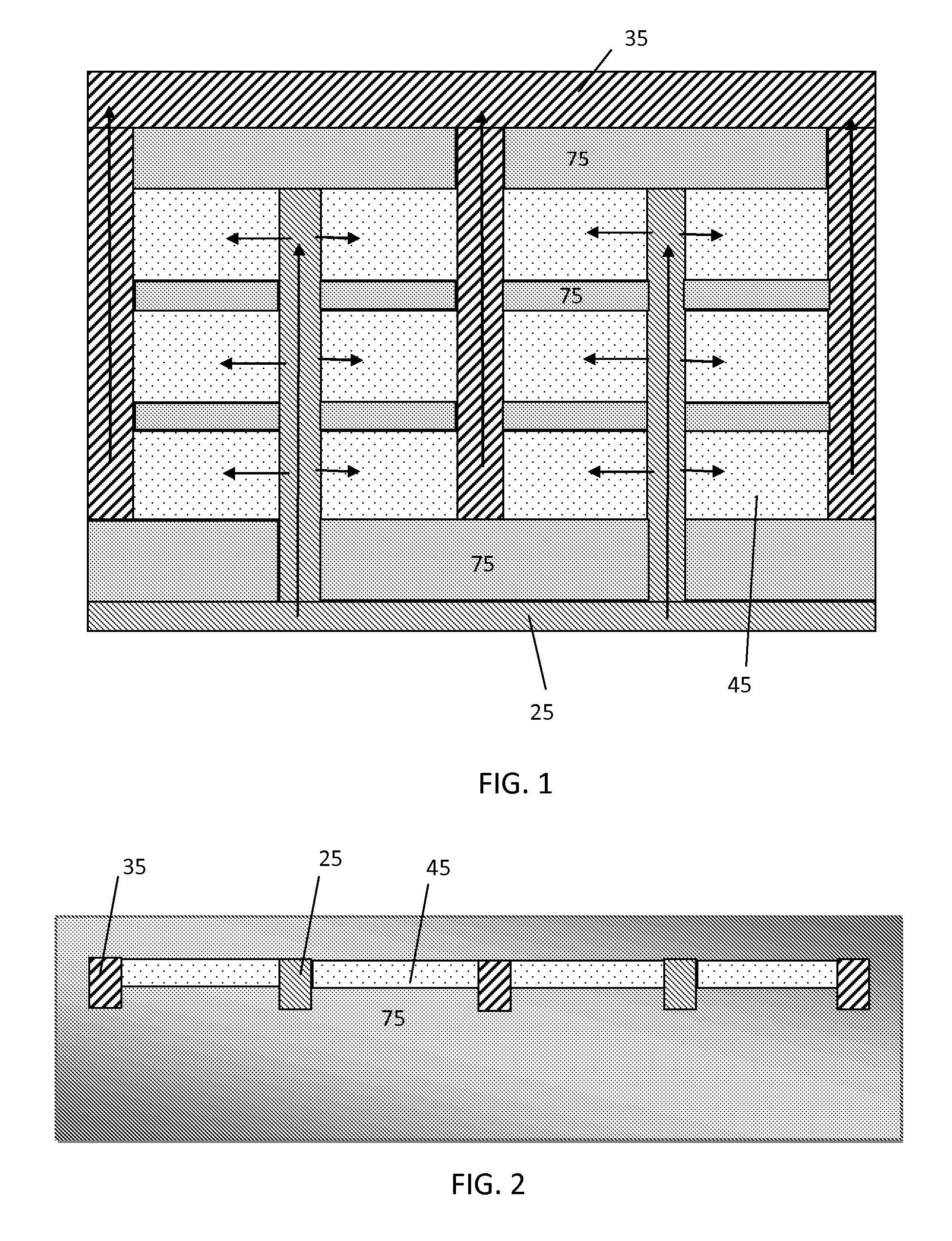
FIG. 1, plan view of cartridge according to a

[0048]Some embodiments of the present invention have analysis areas in the form of an array of microfluidic chambers. This can enable more spacers for a given overall area, and thus help maintain a specified height. These chambers can be coupled in parallel by entry channels, so as to enable rapid filling. A single sampling port can be arranged fluidly connected to the entry channels to allow easy entry of a fluid sample. Venting channels are also arranged. The channels can be in an interdigitated pattern so as to enable more rapid filling of many chambers in parallel. In some cases there is a set of interdigitated fingers for capillary flow of the sample towards the array of analysis areas. The filling is preferably by capillary action. In embodiments of the present invention, filling by capillary action can be defined by capillary filling by a standard aqueous solution such as PBS, e.g. at standard temperature and pressure or optionally...

example

[0079]A device according to the present invention is described in the present example. The device can comprise one entry channel with a length of 55 mm and two analysis chambers of 55 mm width and 4 mm length alongside this channel. A second envisioned and more compact approach is to have two or three entry channels of 28 mm long and four analysis chambers. Each chamber has a 28 mm width entrance and is 4 mm long. Filling time depends on the filling characteristics of the entry channels and the length of the channel that is supplying the blood to the entry channels. An analysis chamber with these large entrance widths and only a length of 4 mm fills very fast, less than few seconds. The necessary time to fill the entry channel of 1 mm width, 28 mm long and a gap 18 micrometer with only capillary forces and a supply channel of 30 mm is 13 sec which fulfill the requirement of a filling time lower that 1 minute. It is most beneficial to have all entry channels to be as small as possibl...


PUM

PropertyMeasurementUnit
heightaaaaaaaaaa
heightaaaaaaaaaa
heightaaaaaaaaaa

Abstract

Apparatus for producing thin layers of a fluid sample for analysis, has a two dimensional array of analysis chambers (45), and a branching pattern of entry channels (25) coupled to the array to enable the analysis chambers to be filled in parallel. The analysis chambers are planar with a height less than that of the entry channels so as to produce the thin layers when filled with the fluid sample. The array enables more spacers between chambers in a given area, so that variations in height of the chambers can be reduced, while still enabling fast filling of the chambers. The analysis chambers can be suitable for capillary filling by a specified fluid sample such as blood. A pattern of exit channels (35) can be coupled to the array. The entry and exit channels can form comb patterns, fingers of the comb patterns being interdigitated, and the analysis chambers being arranged between the interdigitated fingers of the comb patterns.

Description

FIELD OF THE INVENTION[0001]This invention relates to apparatus and methods for preparing thin layers of fluid for analysis and to systems and methods for analyzing such thin layers, especially to methods and apparatus for automated analysis of samples in a cartridge. The present invention particularly relates to apparatus and methods for preparing thin layers, especially monolayers of cells such as red blood cells, e.g. not having overlapping red blood cells, for analysis and to systems and methods for analyzing such thin layers or monolayers of cells, especially to methods and apparatus for automated analysis of samples in a cartridge.BACKGROUND OF THE INVENTION[0002]Cell based analysis can be carried out by staining cells with a specific reagent and inspecting the cell population in a microscope. For imaging-based cell diagnostics, e.g. using a microscope, a camera and a software application for image analysis and diagnosis, it is important to create a monolayer of separated cell...

Claims


Application Information

Patent Timeline
Patent Type & Authority Patents(United States)
IPC IPC(8): G01N33/00B01L3/00G01N1/28G01N21/03
CPCG01N1/2813B01L3/5025G01N21/03B01L2200/026B01L2200/0642B01L2300/0816B01L2300/0829B01L2300/0864B01L2400/0688G01N2021/0346Y10T29/49
Inventor WIMBERGER-FRIEDL, REINHOLDWILLARD, NICOLAAS PETRUSCAMPS, IVO GODFRIED JOZEFLAUBSCHER, MARKUSPEETERS, EMIELPICIU, OANA MIHAELA
Owner KONINK PHILIPS ELECTRONICS NV
Learn More