
Data mining technique with federated evolutionary coordination

a data mining and evolutionary coordination technology, applied in the field of data mining, can solve the problems of increasing the workload of the top-chain evolutionary coordinator pool. , to achieve the effect of reducing the workload of the top-chain evolutionary coordinator pool and reducing the bandwidth requirements

Active Publication Date: 2016-10-11
COGNIZANT TECH SOLUTIONS U S CORP
View PDF22 Cites 31 Cited by
  • Summary
  • Abstract
  • Description
  • Claims
  • Application Information

AI Technical Summary

Benefits of technology

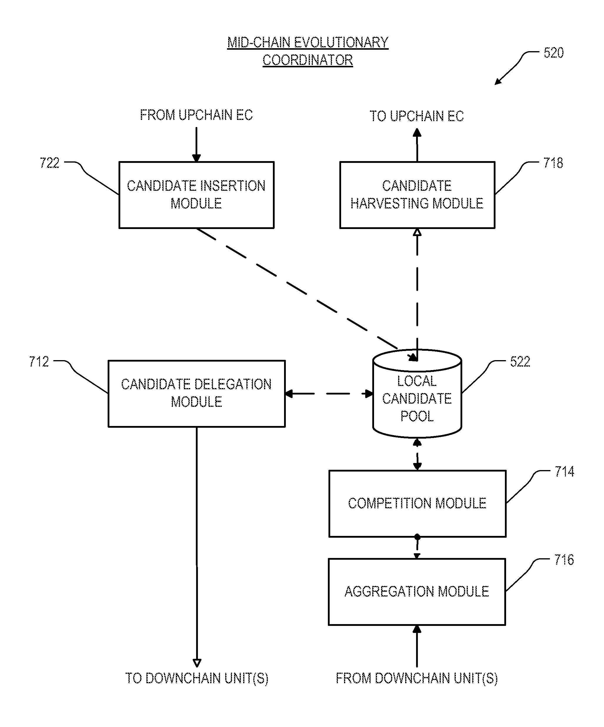
The patent text describes a way to improve the performance of a server by federating its functions. This is done by adding "mid-chain" evolutionary coordinators between the main server and clients. These coordinators help reduce the workload on the top-chain coordinator and also save bandwidth. Multiple levels of these coordinators can be used in a hierarchy, and each has its own pool of candidates to reduce the load on the top-chain coordinator. As a result, the server becomes more efficient and effective in handling requests from clients.

Problems solved by technology

A computer security environment may record a large number of software code examples that have been found to be malicious.
Despite the large quantities of such data, or perhaps because of it, deriving useful knowledge from such data stores can be a daunting task.
In environments having a very large search space for optimal individuals, the computational demands of an evolutionary algorithm can become prohibitive.
One bottleneck of many client / server arrangements arises where the server manages a single instance of the candidate pool, containing what is believed to be the best individuals so far developed.
There is also a problem of bandwidth when too many clients are sending material up to the server cluster, which generally has to be physically near the place where the candidate pool is persisted (e.g., a database server).

Method used


Image

  • Data mining technique with federated evolutionary coordination
  • Data mining technique with federated evolutionary coordination
  • Data mining technique with federated evolutionary coordination

Examples


example embodiment

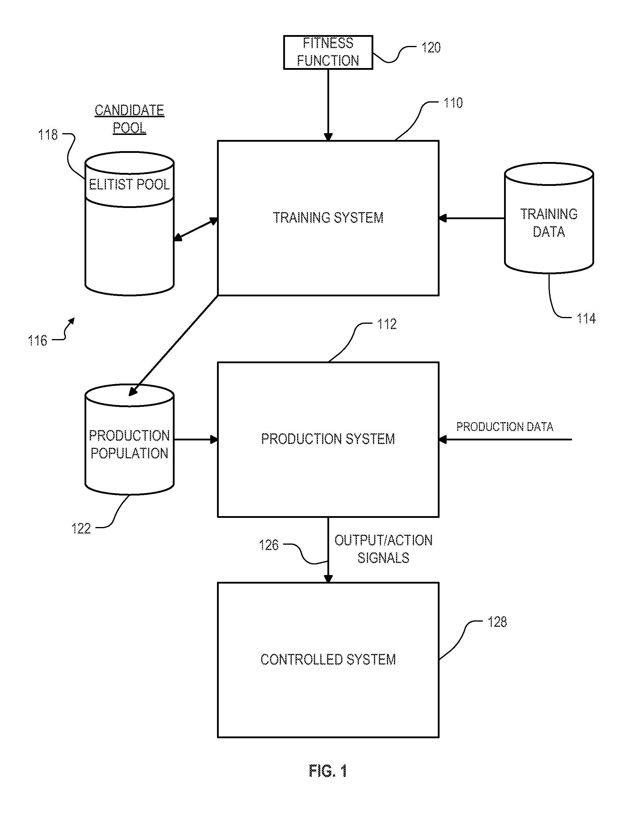
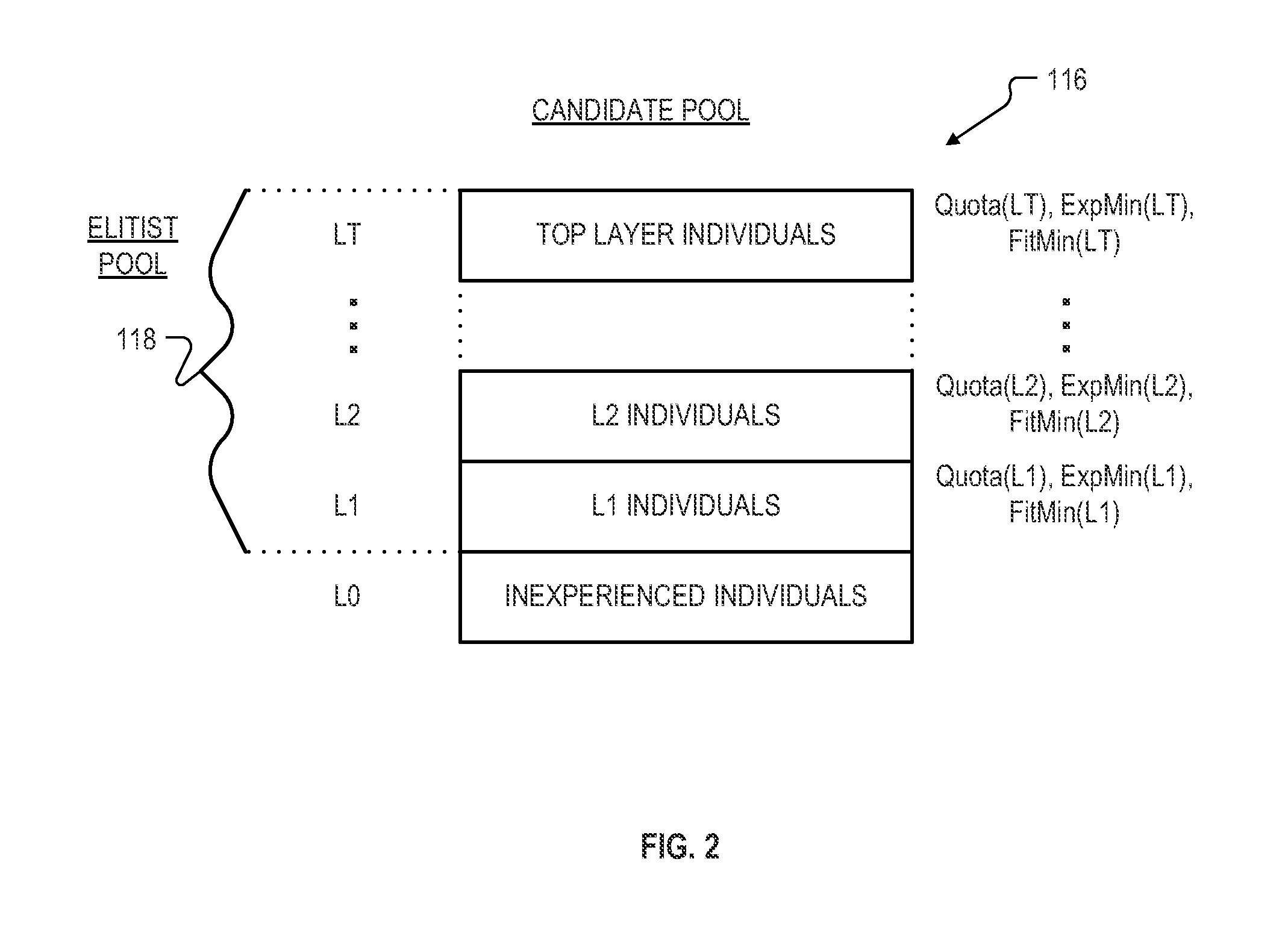
[0039]FIG. 1 is an overall diagram of an embodiment of a data mining system incorporating features of the invention. The system is divided into three portions, a training system 110, a production system 112, and a controlled system 128. The training system 110 interacts with a database 114 containing training data, as well as with another database 116 containing the candidate pool. As used herein, the term “database” does not necessarily imply any unity of structure. For example, two or more separate databases, when considered together, still constitute a “database” as that term is used herein. In particular, though candidate pool 116 may appear in FIG. 1 as a unitary structure, whereas in the federated embodiments described herein it is actually spread over multiple storage units. The candidate pool database 116 includes a portion 118 containing the elitist pool. The training system 110 operates according to a fitness function 120, which indicates to the training system 110 how to ...

example sequence

[0108]Given the above principles, the following is an example sequence of steps that might occur in the arrangement of FIG. 5 as individuals are created, tested, subjected to competition, evolved, and eventually harvested. Many steps are omitted as the system operates on numerous individuals and numerous evolutionary not mentioned herein. Many steps are omitted also in between the steps set forth, for purposes of clarity. In addition, for purposes of clarity several of the evolutionary units in FIG. 5 are referred to by shorthand abbreviations EC1, EC2, EC4, EE2, EE3, EE4, EE5, EE6 and TEC, all as indicated in FIG. 5.

[0109]EE2 creates candidates, including Individual #1, writes to local candidate pool

[0110]EE2 tests the candidates in local candidate pool, including discarding some through local competition, procreating to make new candidates, and creating new candidates randomly

[0111]Individual #1 reaches top layer in local candidate pool

[0112]EE2 transmits candidates from top layer...


PUM


Abstract

Roughly described, a data mining arrangement for developing high quality classifiers using an evolutionary algorithm, includes a plurality of “mid-chain” evolutionary coordinators, down-chain of a main (top-chain) evolutionary coordinator and up-chain of evolutionary engines. Multiple levels of mid-chain evolutionary coordinators can be used in a hierarchy, and the various branches of the hierarchy need not have equal length. Each evolutionary coordinator (other than the top-chain evolutionary coordinator) appears to its up-chain neighbor as if it were an evolutionary engine, though it does not actually perform any evolution itself. Similarly, each evolutionary coordinator (including the top-chain evolutionary coordinator) also appears to its down-chain neighbors as a top-chain evolutionary coordinator. Each mid-chain evolutionary coordinator maintains its own local candidate pool, reducing the load on the top-chain evolutionary coordinator pool, as well as reducing bandwidth requirements. Only the evolutionary engines perform actual testing of candidate individuals on training data.

Description

CROSS-REFERENCE TO OTHER APPLICATIONS[0001]This application is a Continuation-In-Part of U.S. application Ser. No. 12 / 267,287, filed Nov. 7, 2008, entitled “DISTRIBUTED NETWORK FOR PERFORMING COMPLEX ALGORITHMS”, which application is a non-provisional of U.S. Application No. 61 / 075,722, filed Jun. 25, 2008, entitled “DISTRIBUTED NETWORK FOR PERFORMING COMPLEX ALGORITHMS”, and a non-provisional of U.S. Application No. 60 / 986,533, filed Nov. 8, 2007, entitled “DISTRIBUTED NETWORK FOR PERFORMING COMPLEX ALGORITHMS”. All of the above applications are incorporated herein by reference for their teachings.[0002]The following patent applications are also incorporated herein for their teachings:[0003]U.S. application Ser. No. 12 / 769,589, filed Apr. 28, 2010, entitled “DISTRIBUTED EVOLUTIONARY ALGORITHM FOR ASSET MANAGEMENT AND TRADING”;[0004]U.S. application Ser. No. 12 / 769,605, filed Apr. 28, 2010, entitled “CLASS-BASED DISTRIBUTED EVOLUTIONARY ALGORITHM FOR ASSET MANAGEMENT AND TRADING”; a...

Claims


Application Information

Patent Timeline
IPC IPC(8): G06N3/08
CPCG06N3/086G06N3/126G06Q10/0633
Inventor SHAHRZAD, HORMOZHODJAT, BABAK
Owner COGNIZANT TECH SOLUTIONS U S CORP
Learn More