
Oscillator with a detent escapement

a technology of detent escapement and oscillator, which is applied in the field of oscillators, can solve the problems of high thickness and compactness of oscillators

Active Publication Date: 2016-10-11
NIVAROX FAR
View PDF14 Cites 7 Cited by
  • Summary
  • Abstract
  • Description
  • Claims
  • Application Information

AI Technical Summary

Benefits of technology

The present invention proposes an oscillator comprising a resonator and a detent escapement that overcomes drawbacks of existing oscillators. It is reliable, compact, not subject to tripping and its organs are very precisely positioned in relation to each other. The oscillator has very few components for mounting, which also means that the elements of the components are already perfectly referenced in relation to each other. The flexible structures used in the oscillator decrease the required thickness by dispensing with the use of pivots and intrinsically result in the elimination of tripping. The overall oscillator efficiency is increased without decreasing its compactness, making it suitable for use in a wristwatch.

Problems solved by technology

Further, the oscillator is very compact owing to the use of flexible structures, also called monolithic articulated structures, which decreases the required thickness by dispensing with the use of pivots and intrinsically results in the elimination of tripping.

Method used


Image

  • Oscillator with a detent escapement
  • Oscillator with a detent escapement
  • Oscillator with a detent escapement

Examples


first embodiment

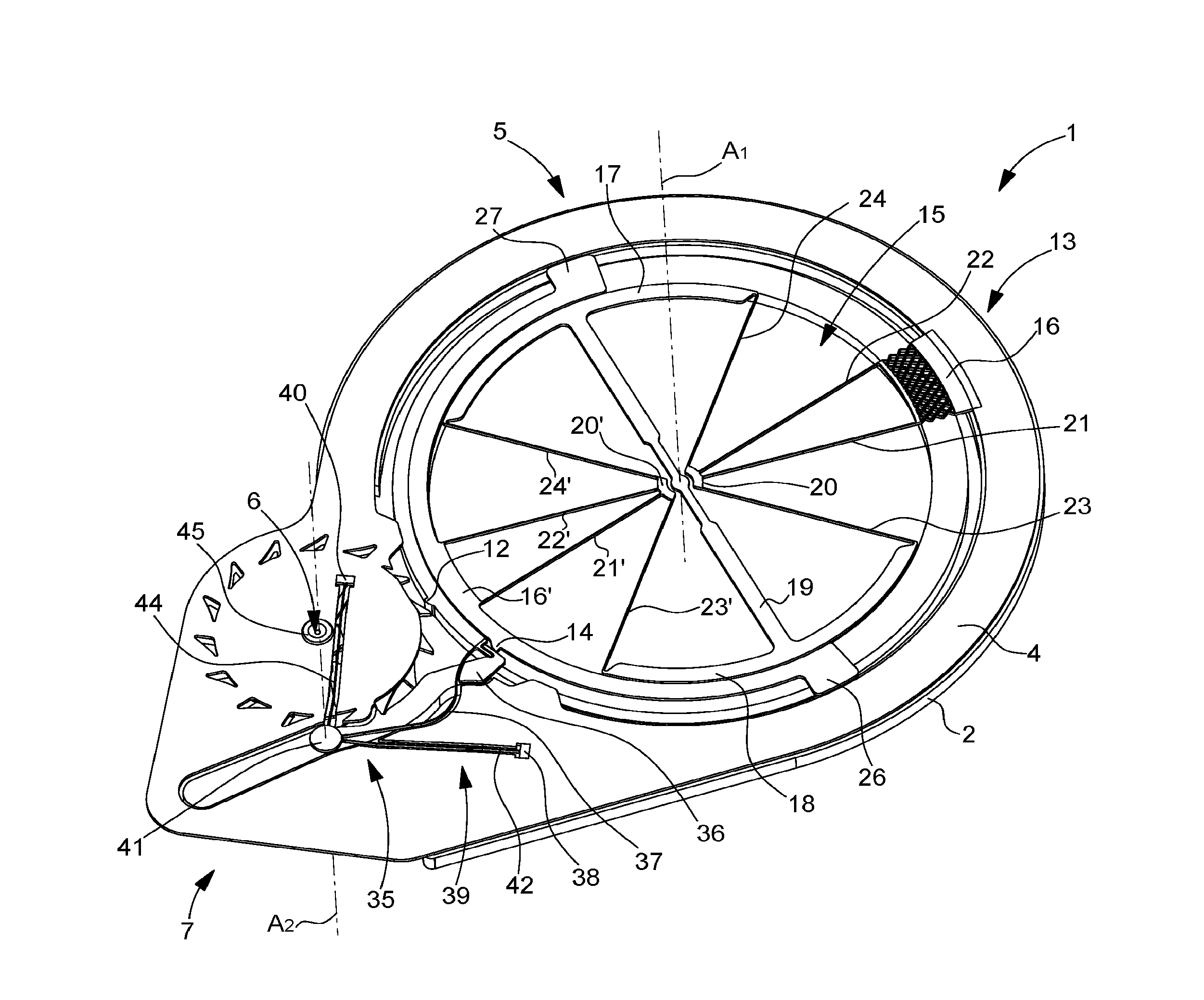
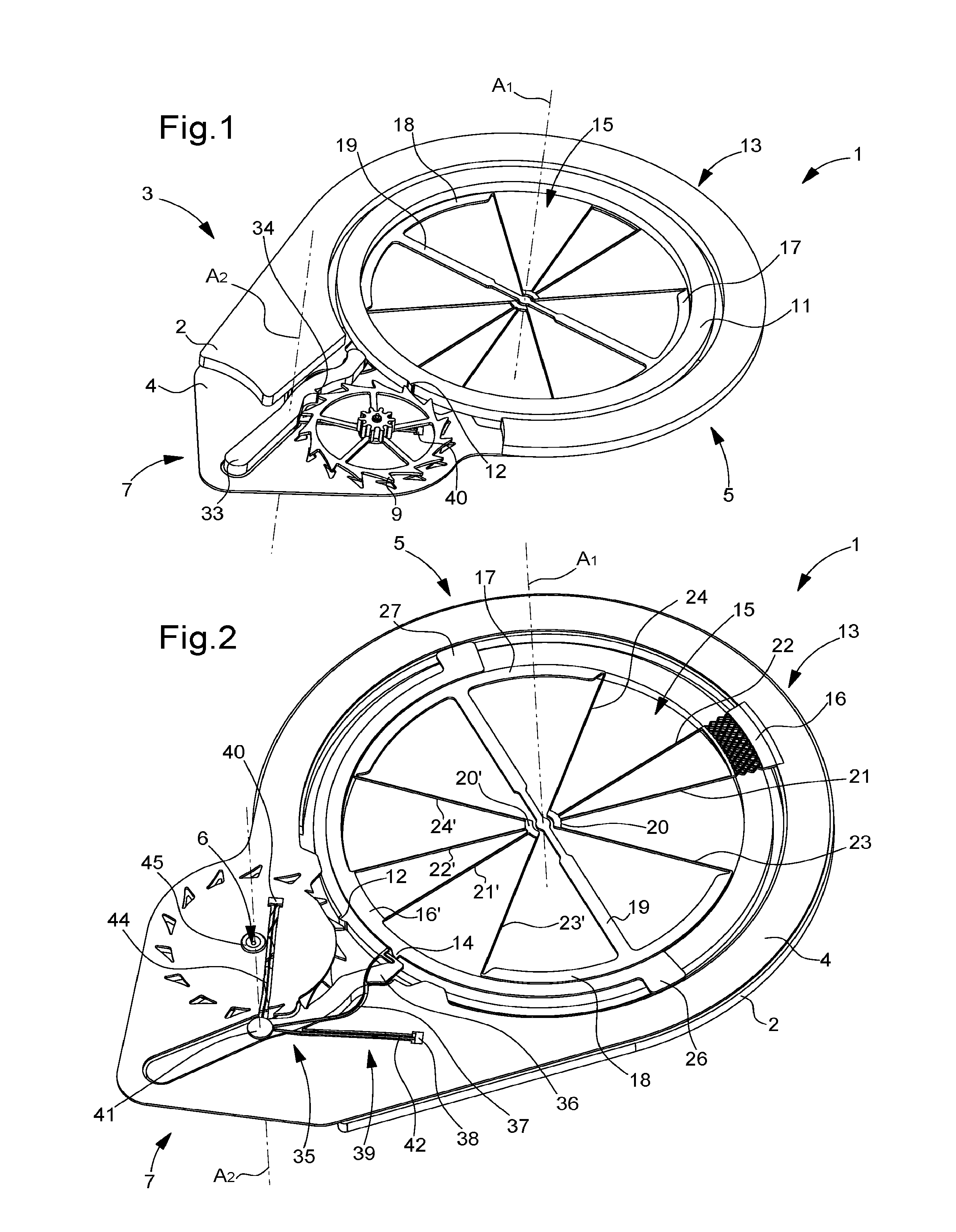
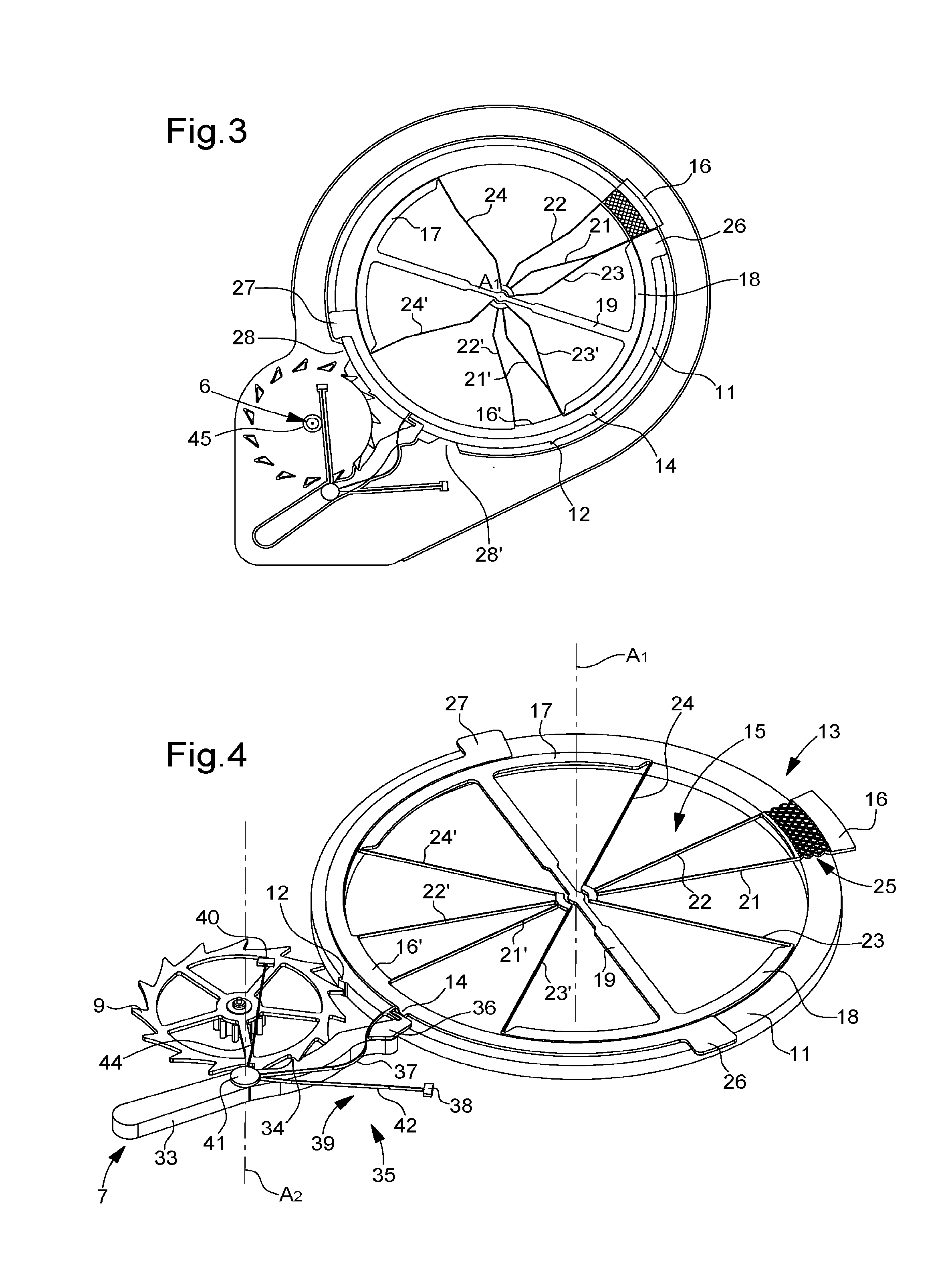
[0046]Two embodiments are shown in FIGS. 1 to 11 to better explain the advantages of the invention. According to the invention illustrated in FIGS. 1 to 6, oscillator 1 comprises a one-piece oscillator assembly 3 formed integrally with a one-piece resonator 5 and a one-piece detent 7 and only in first and second integral plates 2, 4. Further, oscillator 1 comprises an escape wheel 9 which is placed in an aperture 6 of second plate 4.

[0047]One-piece resonator 5 is formed in first and second integral levels, the first level comprising inertia member 11 provided with impulse-pallet 12 and the second level comprising a first flexible structure 13 and discharging-pallet 14. As visible in FIGS. 1, 2 and 4, impulse-pallet 12 is in one-piece on the peripheral surface of inertia member 11 formed by a ring.

[0048]First flexible structure 13 includes at least one anchoring means 16 integral, via flexible means 15, with two arcs 17, 18 connected by a crosspiece 19, said flexible means 15 being a...

second embodiment

[0056]According to the invention illustrated in FIGS. 7 to 11, oscillator 101 comprises a one-piece oscillator assembly 103 formed integrally with a one-piece resonator 105 and a one-piece detent 107 and only in first and second integral plates 102, 104. Further, oscillator 101 comprises an escape wheel 109 which is placed in an aperture 106 of second plate 104.

[0057]As illustrated in FIG. 10, one-piece resonator 105 is formed in first and second integral levels, the first level comprising inertia member 111 provided with impulse-pallet 112 and the second level comprising a first flexible structure 113 and discharging-pallet 114. As seen in FIGS. 9 and 10, inertia member 11 is formed by two sectors 108, 108′ connected by a bar 110, the peripheral surface of one 108′ of sectors 108, 108′ comprising the impulse-pallet 112.

[0058]First flexible structure 113 includes at least one anchoring means 116, 116′ integral, via flexible means 115, with two arcs 117, 118 connected by a crosspiece...


PUM


Abstract

The invention relates to an oscillator comprising a resonator of the inertia-elasticity type cooperating with a detent escapement comprising a detent cooperating with an escape wheel. The resonator is in one-piece and includes an inertia member and a first flexible structure providing the elasticity and forming a virtual pivot axis of the resonator and the detent is in one-piece and includes an unlocking spring and a second flexible structure forming a virtual pivot axis of the detent.

Description

[0001]This application claims priority from European Patent Application No. 15155874.9 filed Feb. 20, 2015, the entire disclosure of which is hereby incorporated herein by reference.FIELD OF THE INVENTION[0002]The invention relates to an oscillator comprising a resonator of the inertia-elasticity type cooperating with a detent escapement.BACKGROUND OF THE INVENTION[0003]Detent escapement systems are known for having brought high precision to marine chronometers in the 18th century by offering a direct impulse and low sensitivity to friction. However, they proved particularly difficult to adjust and sensitive to shocks. Certain marine chronometers have therefore been mounted in a vacuum, in sand or even in gimbal suspensions to prevent the transmission of any shocks causing tripping, i.e. the accidental passing of two escape wheel teeth instead of one, likely to disturb the operation of the timepiece. Thus, given the sensitivity to shocks and the space required for such assemblies, i...

Claims


Application Information

Patent Timeline
Patent Type & Authority Patents(United States)
IPC IPC(8): G04B15/14G04B17/10G04B17/04
CPCG04B15/14G04B17/04G04B17/045G04B17/10G04B15/00G04B15/06G04B43/002
Inventor CUSIN, PIERRE
Owner NIVAROX FAR
Learn More