Ski binding heel unit

a technology of ski bindings and heel units, applied in ski bindings, skiing, sport apparatus, etc., can solve problems such as more severe injuries, and achieve the effect of reducing the length of the lever arm and reducing the length of the knee injury

Active Publication Date: 2016-10-11
KEYSER W MCHENRY +1
View PDF7 Cites 2 Cited by
  • Summary
  • Abstract
  • Description
  • Claims
  • Application Information

AI Technical Summary

Benefits of technology

[0006]The shortcomings of prior art ski bindings with respect to lateral heel release are at least mitigated by an alpine, AT, or tech ski binding that provides additional protection against knee injuries, including injuries to the ACL, MCL, tibial plateau, menisci, and femoral condyles by reducing the length of the lever arm from the snow-surface to the knee. In accordance with the principles of the present invention, additional mitigation of knee injuries is obtained by providing a laterally-releasing heel unit of a ski binding wherein the heel unit has a lowered heel pad.
[0007]The lowered heel pad lateral heel release binding will generally reduce peak strain across the ACL and MCL and generally reduce compressive loading on the tibial plateau, the menisci and femoral condyles by reducing valgus torque and valgus bending moments to the knee. Such lowered configuration generally also allows a reduction in cumulative stress to these musculoskeletal structures, and also serves to reduce the frequency in which a lateral heel release binding needs to release the ski boot (or in an equal-magnitude and opposite-direction perspective—release the ski) because both the frequency and the severity of loading is reduced. Consequently, reducing the frequency of lateral heel releases also serves to mitigate second-order-injury effects during release-events. Second-order-injuries include events such as having the released ski hitting the skier (or hitting other skiers) during the time between when the ski releases and when the ski comes to a full stop; or reducing the need for a skier with only one remaining ski to ski to a controlled stop without first striking a tree, lift-tower, other skier, or from impacting the snow surface. Each such release-event and possible subsequent impact could cause an upper-body or head injury that could result in a more severe injury than an injury to the ACL, MCL, tibial plateau, menisci or femoral condyles.
[0009]In accordance with the principles of the present invention, lowering the heel pad is generally achieved by reducing the “stacking height” of the mechanical elements inside the lower heel housing. Such reduction in stacking height must take into account significant restrictions such as the width limits of narrow skis, whereon a binding heel unit, including the binding heel unit's related ski-brake elements, should not significantly overhang the width of a narrow ski. Furthermore, the lowered lower heel housing should translate, longitudinally, within its mating heel track, as smoothly and as rapidly as possible during rapid flex and counter-flex of the ski, even in the presence of the eccentric lateral loads that cause the lower heel housing to partially-rotate within its corresponding heel track. Partial-rotation should not cause longitudinal jamming in ways similar to the jamming of dresser-drawers. For example, during the induction of an ACL-straining abduction force generated under or near the projected axis of the tibia, the abduction force can sometimes enter the ski-binding-boot-leg system aftward of the effective lateral-centroid of the lower heel housing and heel track assembly thereby potentially causing a jamming-effect unless a novel heel track system is deployed to avert such jamming effect.
[0011]In accordance with the principles of the present invention, the configuration of the interface between the lower heel housing and heel track assembly maximizes the balance of the opposing forces of the eccentrically positioned longitudinal pressure spring against the resultant-refracted force of friction formed at the interfaces between the lower heel housing and heel track—in order to promote smooth longitudinal displacement between the lower heel housing and heel track.

Problems solved by technology

Each such release-event and possible subsequent impact could cause an upper-body or head injury that could result in a more severe injury than an injury to the ACL, MCL, tibial plateau, menisci or femoral condyles.
For example, during the induction of an ACL-straining abduction force generated under or near the projected axis of the tibia, the abduction force can sometimes enter the ski-binding-boot-leg system aftward of the effective lateral-centroid of the lower heel housing and heel track assembly thereby potentially causing a jamming-effect unless a novel heel track system is deployed to avert such jamming effect.

Method used


Image

  • Ski binding heel unit
  • Ski binding heel unit
  • Ski binding heel unit

Examples


Embodiment Construction

[0028]A novel alpine, AT or ‘tech’ ski binding heel unit will be described hereinafter. Although the invention is described in terms of specific illustrative embodiments, it is to be understood that the embodiments described herein are by way of example only and that the scope of the invention is not intended to be limited thereby.

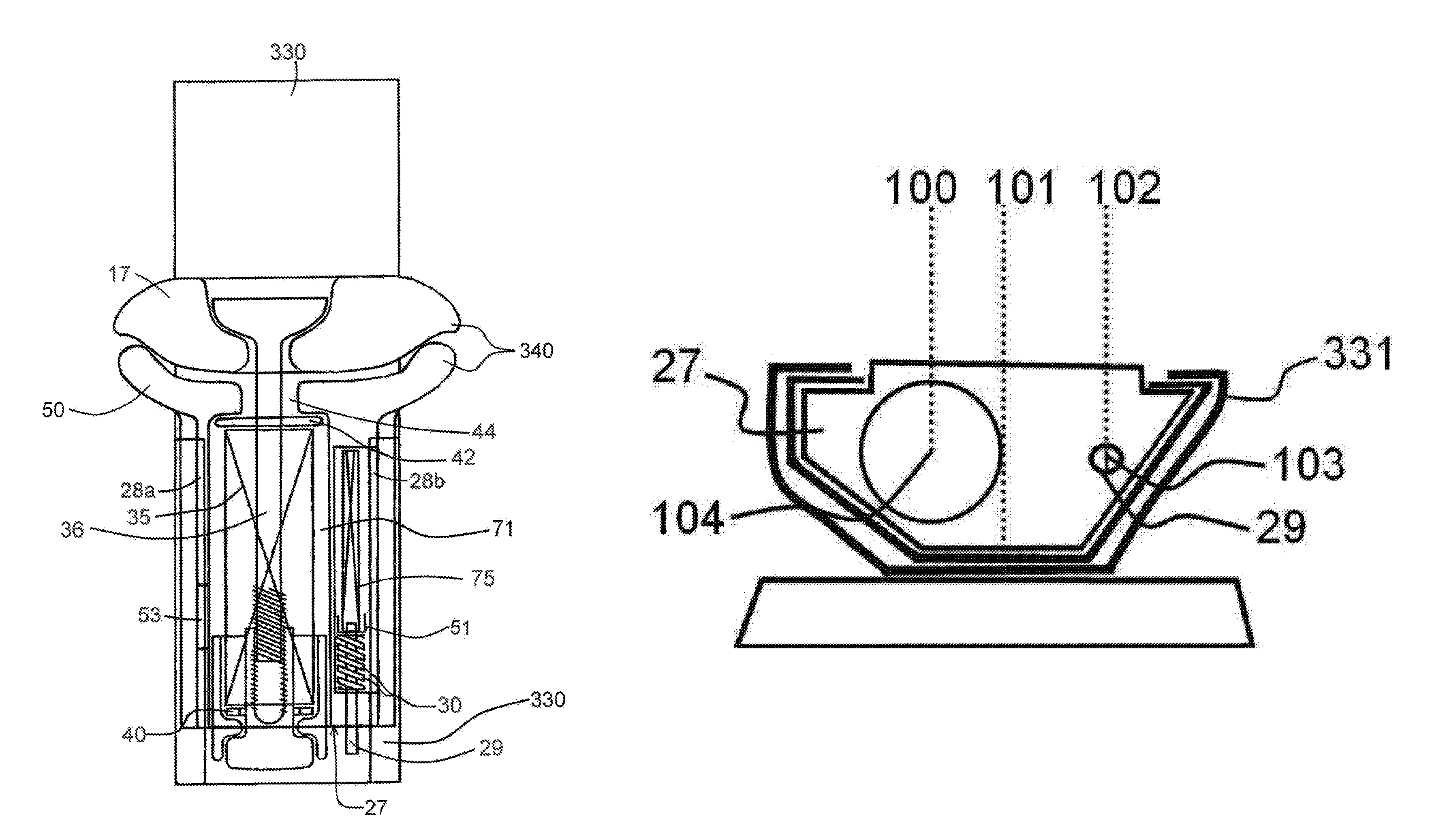
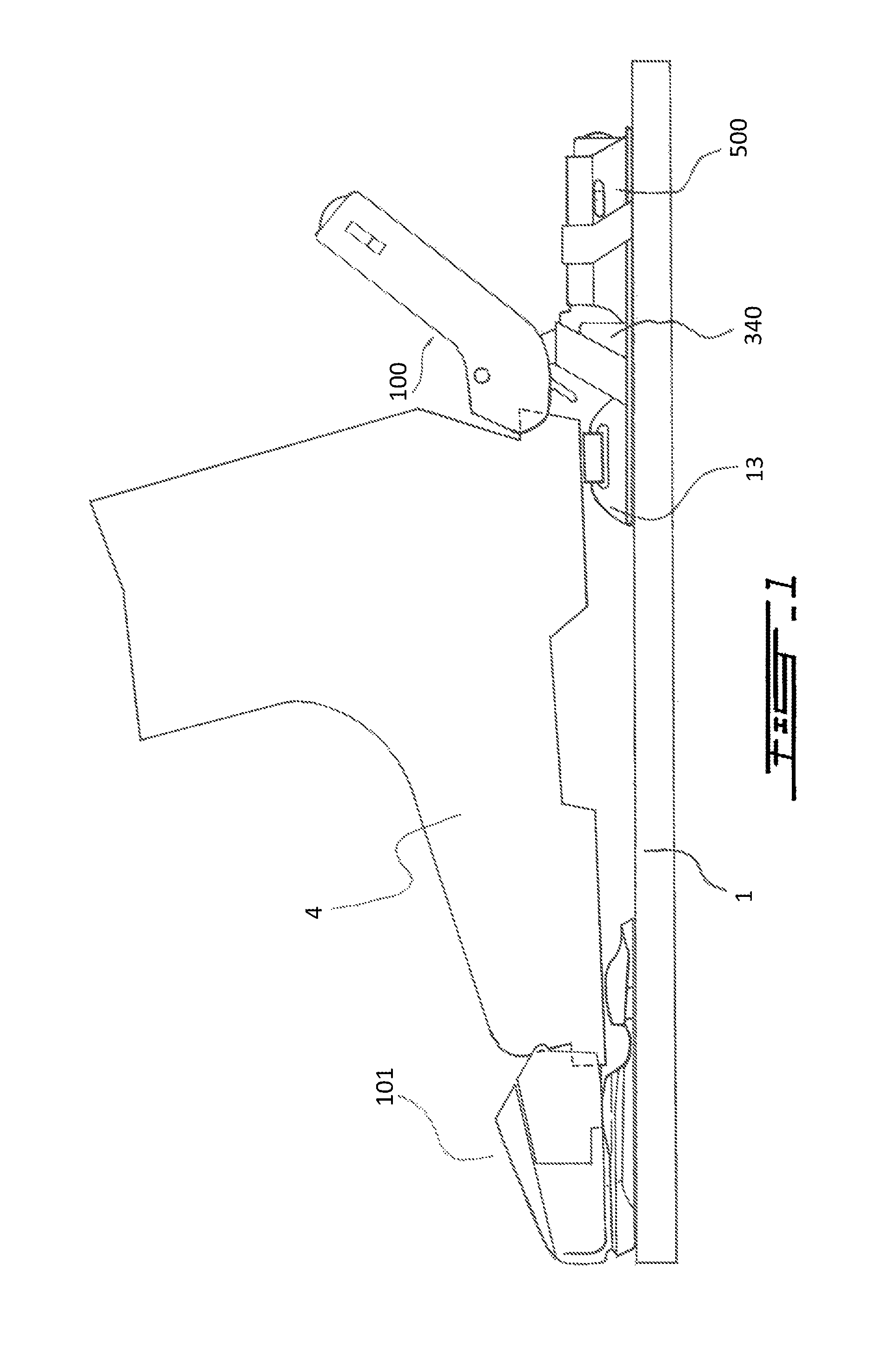
[0029]Now referring to FIG. 1, a ski binding comprising a toe unit 101 and a heel unit 100 is shown. In accordance with the present invention, the top surface of heel pad 13 has been lowered as a result of the lowered support structure 500 that houses the lateral heel release mechanism 340 (FIG. 2) and longitudinal pressure spring 75 (FIG. 7).

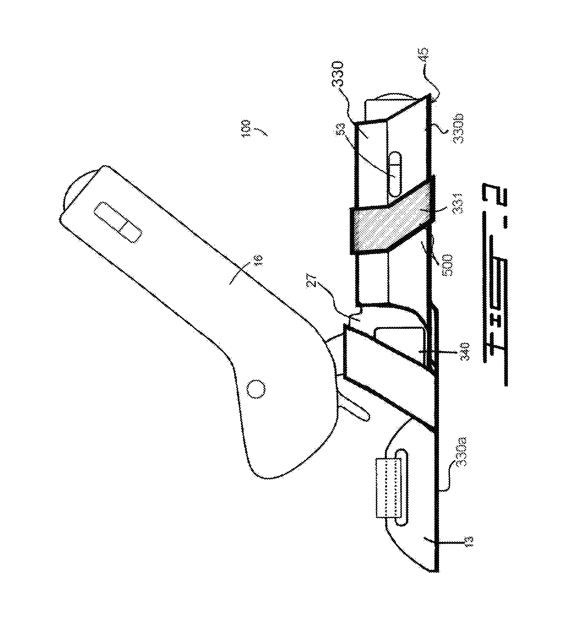
[0030]Now referring to FIGS. 2 and 3, the heel unit 100 comprises an upper heel housing 16, a lower heel housing 27, a heel pad 13, and a heel track 330. The lower heel housing 27 contains at least one lateral release mechanism 340. The heel pad 13 is connected or fixed to the heel track 330. The heel track 330 compri...


PUM


Abstract

An improved ski binding heel unit comprising a lateral heel release mechanism to release the heel of a ski boot from a ski is disclosed. The ski binding heel unit typically includes an independent vertical heel release mechanism, an independent lateral heel release mechanism, and a longitudinal pressure compensator. The improved ski binding heel unit allows a reduction in the height of the heel pad. This reduction in heel pad height is generally achieved by eccentrically positioning two or more of the springs within the heel unit while superpositioning the resultant centroid of the forces of friction between the lower housing and mating heel track structures that house at least one of the eccentrically positioned springs to foster smooth longitudinal displacement of the lower heel housing when the ski flexes and counterflexes.

Description

CROSS-REFERENCE TO RELATED APPLICATIONS[0001]The present patent application claims the benefits of priority of commonly assigned U.S. patent application Ser. No. 61 / 803,922, entitled “SKI BINDING HEEL UNIT” and filed at the United States Patent and Trademark Office on Mar. 21, 2013.FIELD OF THE INVENTION[0002]The present invention generally relates to alpine ski bindings, all-terrain (AT) ski bindings, tech-bindings and, in particular, to multi-directional release alpine, AT and tech ski binding heel units that release in the vertical and lateral directions.BACKGROUND OF THE INVENTION[0003]Toe-heel type bindings that provide lateral heel release and which mitigate inadvertent pre-release have been proposed. However, during aggressive edging on hard-pack snow or ice, or especially in the presence of Phantom Foot or Slip-Catch events (for more information about these injury mechanisms, please refer to: Effect of Ski Binding Parameters on Knee Biomechanics; A Three-Dimensional Computat...

Claims


Application Information

Patent Timeline
Patent Type & Authority Patents(United States)
IPC IPC(8): A63C9/08A63C9/084A63C9/00
CPCA63C9/0844A63C9/001A63C9/007
Inventor HOWELL, RICHARD J.
Owner KEYSER W MCHENRY
Why Eureka
Try Eureka