
Electrical connector

a technology of electrical connectors and connectors, applied in the direction of cross-talk/noise/interference reduction, coupling device connection, printed circuit aspects, etc., can solve the problems of lower contact reliability and high cost, and achieve the effect of reducing the total surface reducing the cost of plating, and reducing the area of the connecting section

Active Publication Date: 2016-09-13
HIROSE ELECTRIC GROUP
View PDF15 Cites 4 Cited by
  • Summary
  • Abstract
  • Description
  • Claims
  • Application Information

AI Technical Summary

Benefits of technology

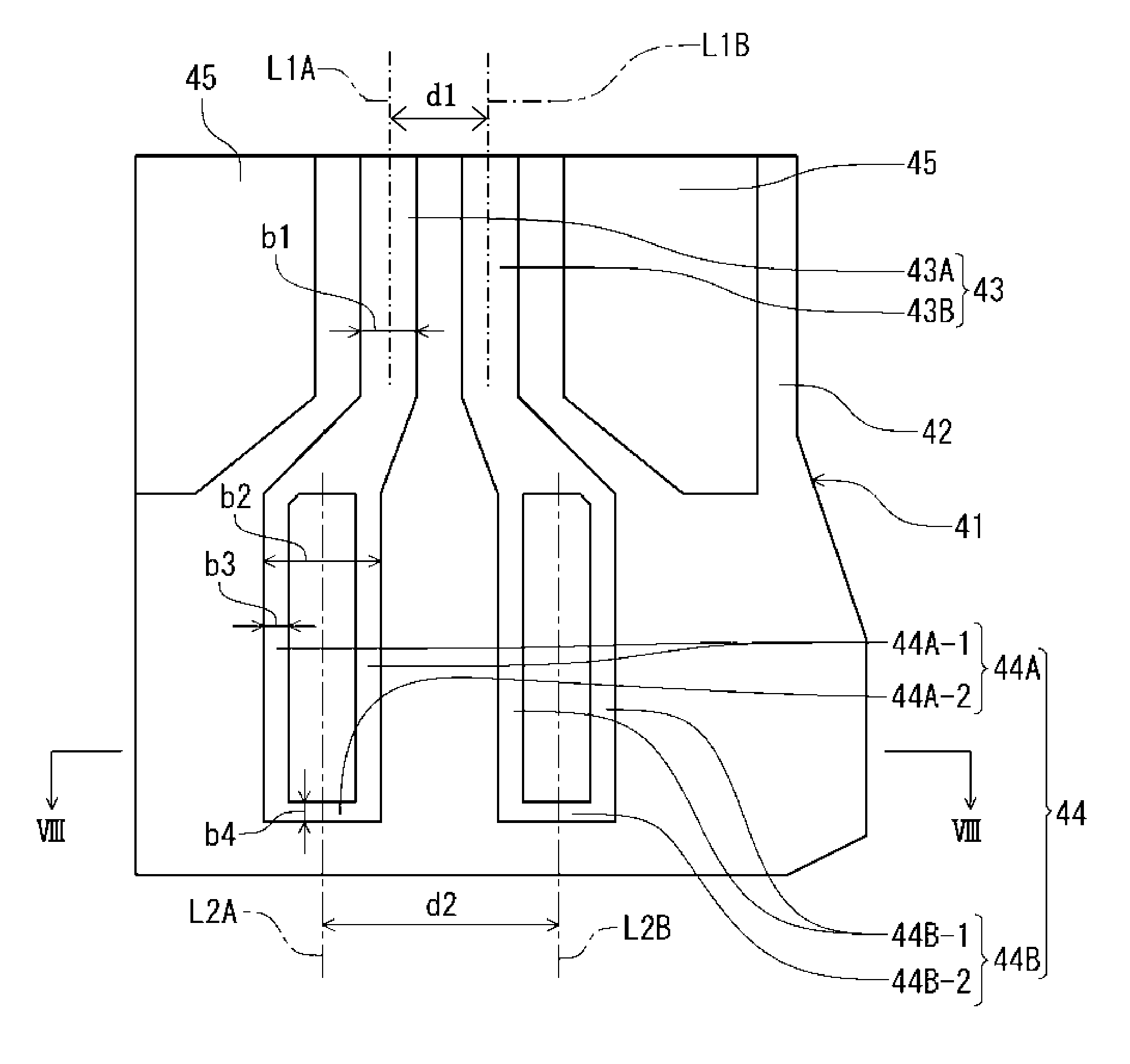
The present invention provides a circuit board design that reduces the area of connecting sections and increases contact surface pressure, improving contact reliability while reducing plating cost. The design also allows for increased allowable displacement and formation of insulating areas between conductive thin sections to further reduce plating cost. The design also includes a grounding plate that covers the range where transmission paths are arranged, reducing the plating area on both surfaces of the circuit board.

Problems solved by technology

Therefore, although it is possible to adjust and improve the impedance, there are issues as follows.
First, since the connecting sections have a large area, when all of the connecting sections are formed on a circuit board surface by plating, a total plating area has to be increased, which results in higher cost.
However, the contact surface pressure has to be small, and thereby there is an issue of lower contact reliability.

Method used


Image

  • Electrical connector
  • Electrical connector
  • Electrical connector

Examples


Embodiment Construction

[0026]Hereunder, an embodiment of the present invention will be described with reference to the accompanying drawings.

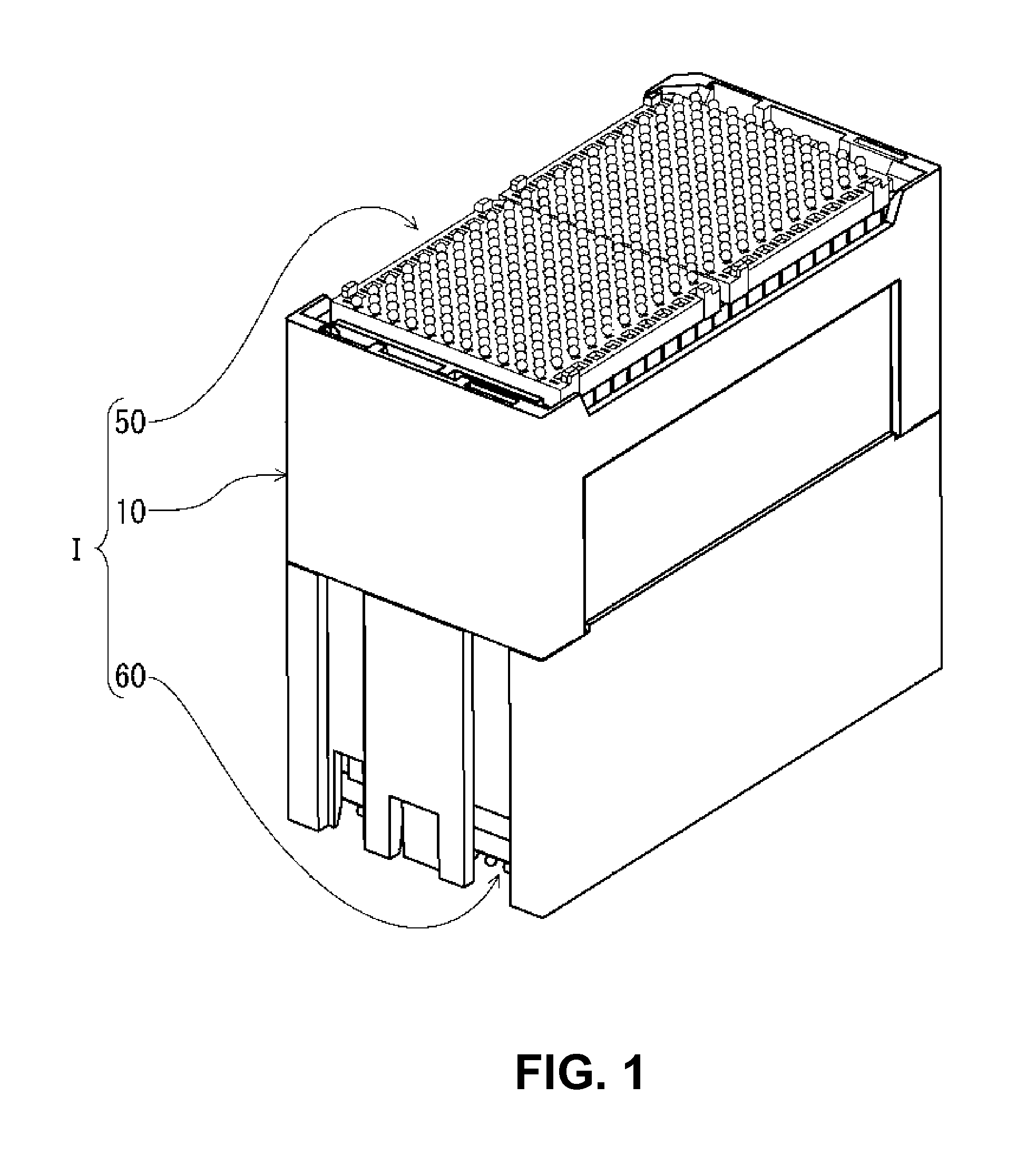
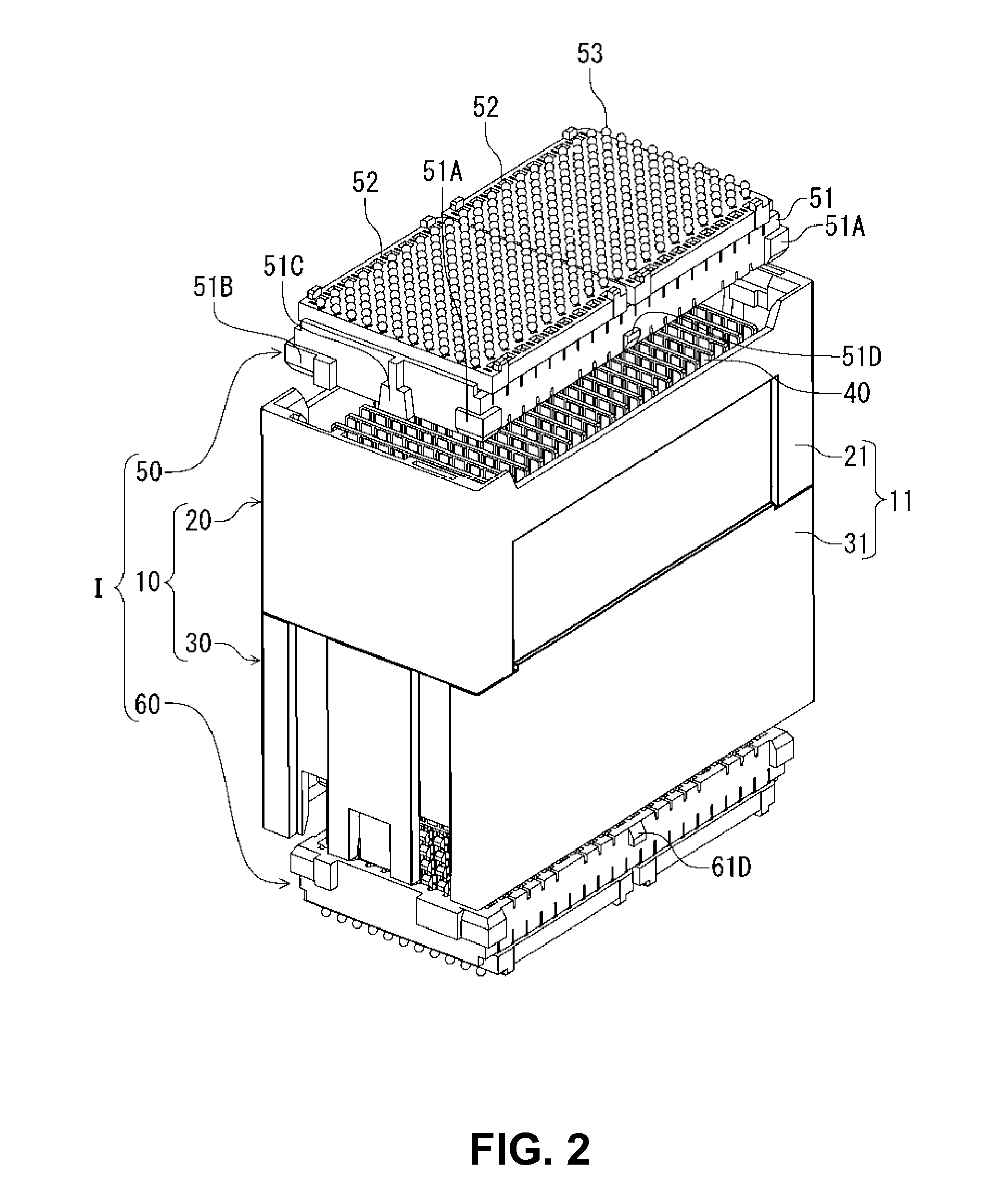
[0027]FIG. 1 is a perspective view showing a state after assembling of a connector assembled component I composed of a connector 10 according to the embodiment, which hold circuit members having transmission paths formed thereon, and mating connectors 50 and 60 that are mating connecting members connected to the connector 10 from thereabove and thereunder, respectively. Both of the mating connectors 50 and 60 hold bottom plates 52 and 62, on which terminals are mounted. Connecting the mating connectors 50 and 60 to the connector 10 from thereabove and thereunder, the two bottom plates 52 are connected via the connector 10. On the other hand, upon use, one mating connector 60 is attached onto a circuit board (not illustrated) provided under the connector 10, and the other mating connector 50 is attached to a circuit board (not illustrated) provided above the connector...


PUM


Abstract

An electrical connector is to be connected to a mating connector. The electrical connector includes a circuit board member formed of an insulation plate member; and a holding member for holding the circuit board member. The circuit board member includes a connecting portion to be connected with a mating connector of the mating connector. The connecting portion includes a pair of conductive band portions and a first insulation region disposed between the conductive band portions.

Description

BACKGROUND OF THE INVENTION AND RELATED ART STATEMENT[0001]The present invention relates to an electrical connector, in which a flat circuit board such as a circuit board member having a board circuit configuration is held with a holding member. In particular, the present invention relates to an electrical connector, in which a flat circuit board such as a circuit board member having a board circuit configuration suitable for high-speed transmission is held with a holding member.[0002]As a conventional board circuit configuration in a circuit member of a connector of this type, for example, there is known a conventional circuit configuration disclosed in Patent Reference. The conventional circuit configuration of Patent Reference 1 is the most common and simple configuration, and has a plurality of transmission paths only on one surface of the circuit board and a grounding plate all over the other surface thereof by plating, without having transmission paths in an inner layer of the...

Claims


Application Information

Patent Timeline
Patent Type & Authority Patents(United States)
IPC IPC(8): H01R12/70H05K1/02
CPCH01R12/7082H05K1/0245H05K1/0219H05K2201/09245H05K2201/09336
Inventor TAMAI, NOBUHIRO
Owner HIROSE ELECTRIC GROUP
Learn More