
Target-image detecting device, control method and control program thereof, recording medium, and digital camera

a technology of target objects and detection results, applied in color televisions, instruments, television systems, etc., can solve problems such as poor visual quality, temporary failure of detection, and erroneous detection, and achieve the effect of preventing the output of a detection result of an erroneously detected target obj

Active Publication Date: 2016-08-30
ORMON CORP
View PDF6 Cites 0 Cited by
  • Summary
  • Abstract
  • Description
  • Claims
  • Application Information

AI Technical Summary

Benefits of technology

The present invention provides a target-image detecting device that can prevent output of a detection result of an erroneously detected target image. The device receives a sequence of photographed images and detects a target image in each image. It decides whether the detection result of a target image of the same target object is included in a predetermined number of detection results. If the detection result is included, it outputs it as a proper detection; if not, it does not output it. This prevents output of an erroneously detected target object. Additionally, the device can accumulate identification information for identifying the detected target image and make the decision based on this information, which allows for quick processing and operation. The technical effect is prevention of output of erroneously detected target object.

Problems solved by technology

In such a technique of automatic recognition, there are cases of occurrence of erroneous recognition (erroneous detection), and occurrence of a temporary failure of recognition (detection).
As a result, visual quality is poor.
Even when an image is a target image to be detected, the image is not always continuously detected, and cannot be temporarily detected in some cases.
In this case, a detection mark such as a detection frame temporarily disappears, and poor visual quality may occur.

Method used


Image

  • Target-image detecting device, control method and control program thereof, recording medium, and digital camera
  • Target-image detecting device, control method and control program thereof, recording medium, and digital camera
  • Target-image detecting device, control method and control program thereof, recording medium, and digital camera

Examples


example 1

(Example 1)

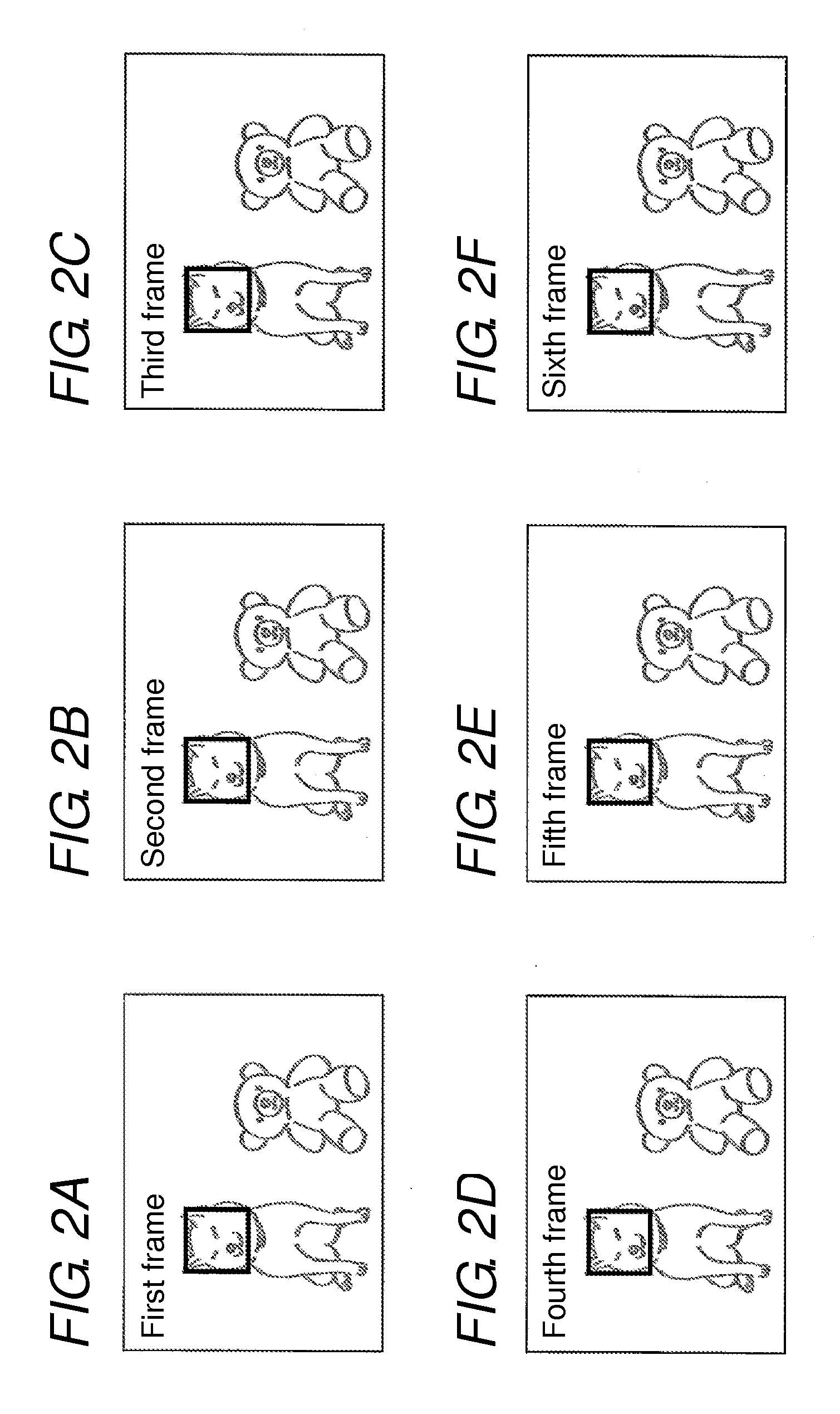
[0061]Next, an example of the operation of the proper-detection deciding unit 32 is described with reference to FIG. 5. FIG. 5 is a view showing, in a table form, an example of data that is input and output by the proper-detection deciding unit 32 for each frame. The example of FIG. 5 corresponds to the example of FIGS. 2A-2F.

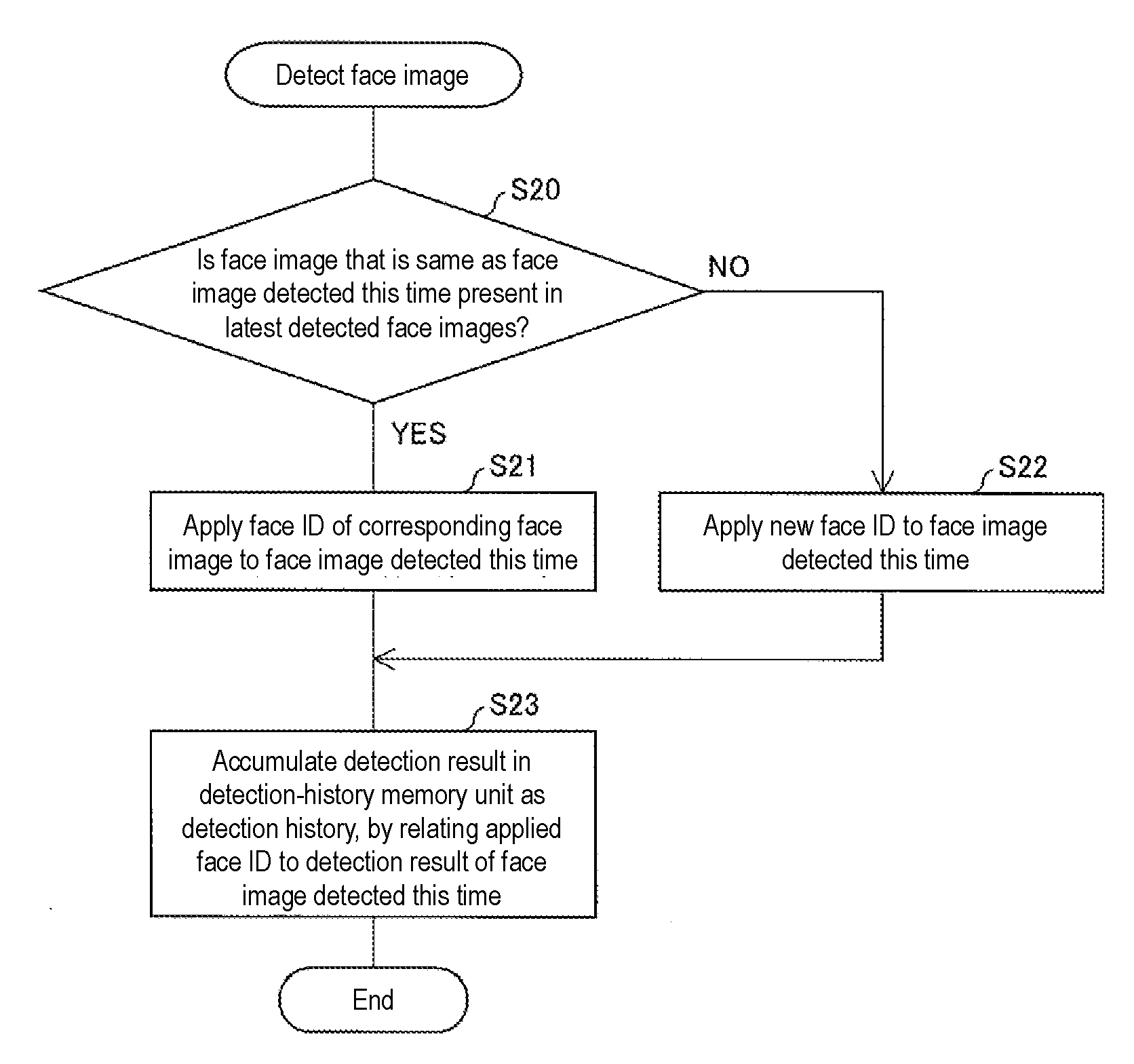
[0062]In the example shown in FIG. 5, the face detecting unit 31 applies ID1 as the face ID to the face image of the dog that is detected in the first frame and that is traced afterward. The face detecting unit 31 applies ID2 as the face ID of the face image of the stuffed toy of the bear, when the face image is detected in the second frame. Since the face image is not able to be detected in the third to fifth frames, the face image cannot be traced. Therefore, when the face image is detected in the sixth frame, ID3 that is different from ID2 is applied as a face ID.

[0063]In the example of FIG. 5, the proper-detection deciding unit 32 does not output...

example 2

(Example 2)

[0064]Next, another example of the operation of the proper-detection deciding unit 32 is described with reference to FIG. 6. FIG. 6 is a view showing, in a table form, an example of data that is input and output by the proper-detection deciding unit 32, for each frame. In the example of FIG. 6, when a face image detected this time is also detected in latest one frame, that is, when a face image is detected continuously in two frames, the proper-detection deciding unit 32 decides that the face image is a properly detected face image.

[0065]In the example of FIG. 6, ID1 is input in the first frame, but latest one frame is not present. Therefore, the proper-detection deciding unit 32 does not output any face ID, by deciding that a face image has not been detected. In the second, fourth, sixth, eighth, tenth, and twelfth frames, since no face ID has been input as undetected, the proper-detection deciding unit 32 does not output any face ID, by deciding that a face image has no...

example 3

(Example 3)

[0069]Next, an example of the operation of the proper-detection deciding unit 32 according to one or more embodiments of the present invention is described with reference to FIG. 7. FIG. 7 is a view showing, in a table form, an example of data that is input and output by the proper-detection deciding unit 32, for each frame. In the example shown in FIG. 7, when a face image detected this time is detected in at least two frames out of latest four frames, the proper-detection deciding unit 32 decides that the face image is a properly detected face image.

[0070]In the example of FIG. 7, latest two frames are not present in the first and second frames. Therefore, the proper-detection deciding unit 32 does not output any face ID, by deciding that a face image has not been detected. In the third and fourth frames, ID1 is input in only one frame out of latest frames, and therefore, no face ID is output. As a result, the proper-detection deciding unit 32 does not output any face I...


PUM


Abstract

A method for controlling a target-image detecting device configured to detect a target image as a part of photographed images and as an image of a target object from the photographed images, includes sequentially obtaining a plurality of the photographed images that form a moving image, detecting a target image included in the obtained photographed image, generating a detection result and accumulating the generated detection result in memory as detection history, referring to the detection history of the memory and deciding whether the detection result of the target image of the same target object is included in a latest predetermined number of detection results, outputting the detection result when the detection result is included, and not outputting the detection result when the detection result is not included.

Description

BACKGROUND[0001]1. Field[0002]The present invention relates to a target-image detecting device that detects a target image as a part of photographed images and as an image of a target object from the photographed images, a control method and a control program of the target-image detecting device, a recording medium, and a digital camera.[0003]2. Related Art[0004]Conventionally, in order to provide a user interface that can be easily used and to automatically obtain an optimum image in an imaging device, a display device, and the like, there has been an increasing need for automatically recognizing a photographing target or a display target. As an example of such a need, there are functions of detecting a face image (target image) as an image of a face (target object) such as a person and an animal, adjusting the detected face image to obtain optimum focus and exposure, recognizing a character (target image), and automatically setting the recognized region as an object of OCR (Optica...

Claims


Application Information

Patent Timeline
Patent Type & Authority Patents(United States)
IPC IPC(8): G06K9/00G06K9/03H04N5/907H04N9/804H04N5/232H04N5/77
CPCH04N5/23219H04N5/772H04N5/907H04N9/8047G06K9/00261G06K9/03G06V40/167H04N23/611
Inventor TANAKA, KIYOAKI
Owner ORMON CORP
Learn More