Cutting insert for tooth cutters

a cutting insert and tooth cutter technology, applied in the field of cutting inserts, can solve problems such as increased costs, and achieve the effects of increasing the number of usable cutting edges, rational and consequently more economic use of cutting inserts, and not requiring a large amount of additional expenditur

Active Publication Date: 2016-08-30
KENNAMETAL INC
View PDF20 Cites 7 Cited by
  • Summary
  • Abstract
  • Description
  • Claims
  • Application Information

AI Technical Summary

Benefits of technology

[0009]The invention is based on the knowledge that cutting edges can be provided not only on one or on two circumferential surfaces of a cuboid basic body, but on all four circumferential surfaces. The increased number of usable cutting edges per cutting insert allows for more rational and consequently more economic use of the cutting inserts.
[0015]It is not only the multiple usability through the provision of multiple cutting edges that contributes to the efficiency of cutting inserts, but also the production of the cutting inserts. In particular, it should be possible to carry out the forming of the cutting edges with as few operating steps as possible. According to a particularly preferred embodiment of the cutting insert according to the invention, a passage opening extends from the one top surface to the other top surface, and the top surfaces have a conical surface portion, wherein the center axis of the cone coincides with the center axis of the passage opening and the conical surface portion is not interrupted in the circumferential direction with reference to the center axis of the cone. Such an advantageous configuration makes it possible to produce all cutting edges associated with one top surface in one single operating step. To this end, the cutting insert is clamped in a grinding tool with the aid of the central passage opening such that it can be rotated about the center axis of the passage opening. In this way, the entire conical surface portion with all associated cutting edges can be ground by the cutting insert being rotated by at least 360° in relation to a grinding surface which is set in a slightly inclined manner, without the cutting insert having to be removed from the tool and re-clamped. The cutting insert has to be turned once just for the production of the conical surface portion and the cutting edges on the opposite side of the basic body.
[0020]Special machining of the edges between the circumferential surfaces, where a bevel surface, which is aligned at an angle of 45° with respect to the associated circumferential surfaces, is formed between two adjacent cutting edges, allows for an ordered overlapping of several cutting inserts arranged one behind the other in the tooth cutter for a high cutting accuracy and surface quality.

Problems solved by technology

On account of the rapid wear of the cutting edges, the number of required cutting inserts is relatively high, which leads to increased costs.

Method used


Image

  • Cutting insert for tooth cutters
  • Cutting insert for tooth cutters
  • Cutting insert for tooth cutters

Examples


Embodiment Construction

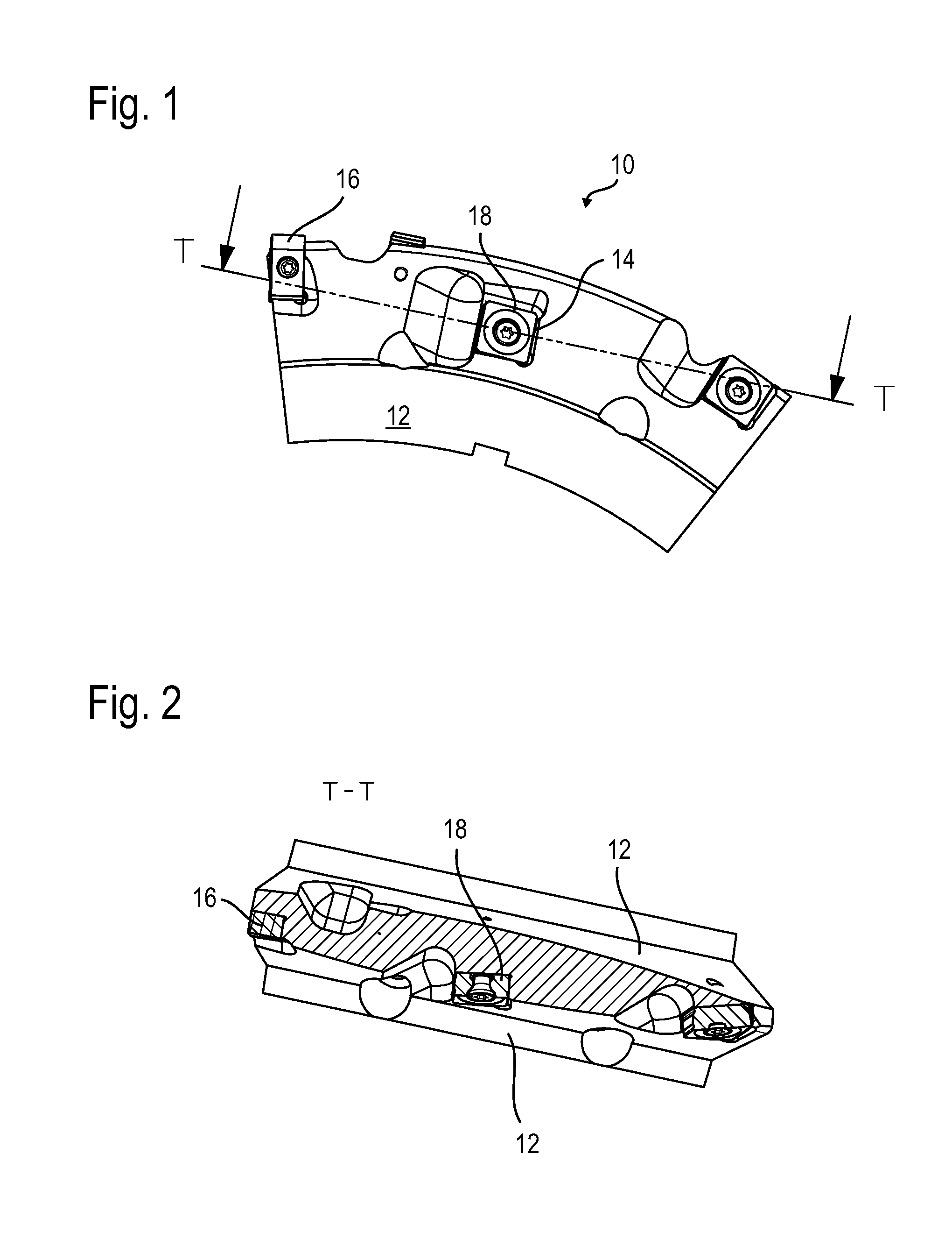
[0026]FIG. 1 shows a representative sector of a substantially disk-shaped tooth cutter 10. As can also be seen from FIG. 2, the two side walls 12 of the tooth cutter 10 have seats realized as receiving pockets 14 for the reception of cutting inserts. In the exemplary embodiment shown, both tooth tip machining cutting inserts 16 and tooth profile machining cutting inserts 18, which are set in each case in an inclined manner with respect to the center plane of the tooth cutter 10, are arranged in the circumferential direction of the tooth cutter 10.

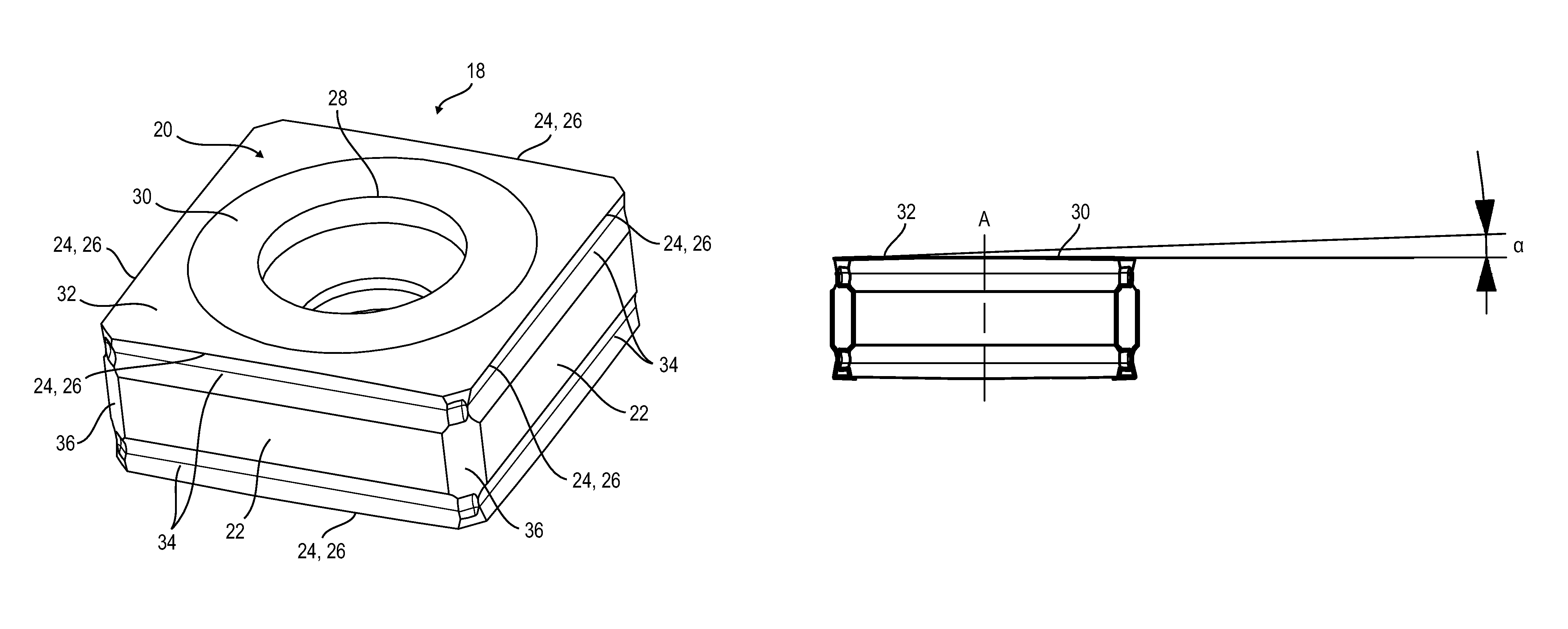
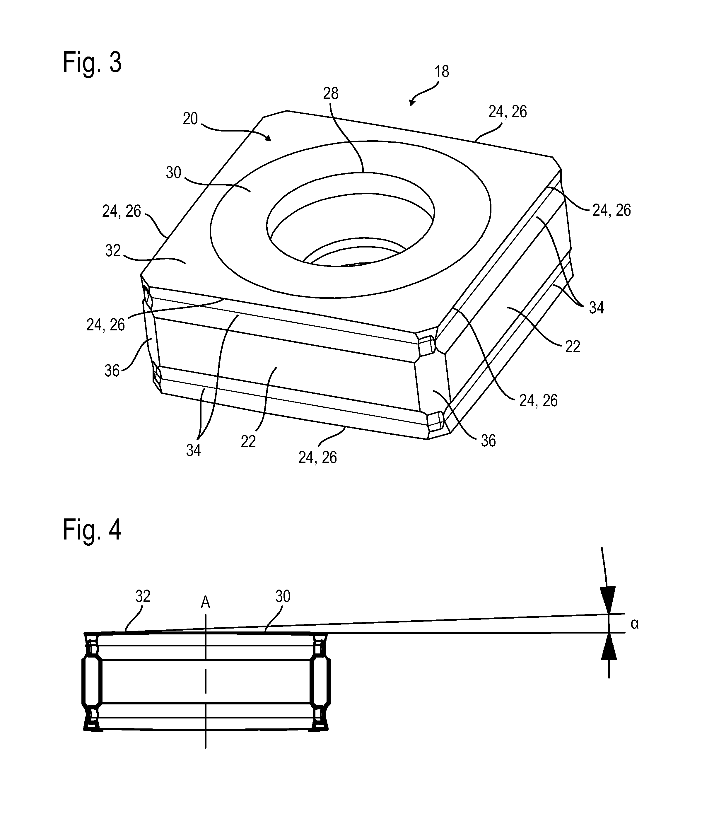
[0027]The following explanations relate only to the cutting inserts 18 for tooth profile machining, one cutting insert 18 of which is shown on its own in FIGS. 3 and 4.

[0028]The cutting insert 18 has a substantially cuboid basic body with a cuboid base. The basic body is defined by two top surfaces 20 on sides opposite each other and four circumferential surfaces 22. Each circumferential surface 22 extends from an edge portion 24 of the one...


PUM

PropertyMeasurementUnit
angleaaaaaaaaaa
radiusaaaaaaaaaa
radiusaaaaaaaaaa

Abstract

A cutting insert for tooth cutters includes a substantially cuboid basic body. The basic body has two top surfaces on sides opposite each other. The basic body also has four circumferential surfaces which extend in each case from an edge portion of the one top surface to an edge portion of the other top surface. A cutting edge is formed at at least one transition from each circumferential surface to one of the top surfaces.

Description

CLAIM TO PRIORITY[0001]This application is a National entry application of German Application No. 102011107789.1, filed on Jul. 18, 2011, the entire contents of which is incorporated herein by reference.FIELD OF THE INVENTION[0002]The invention relates to a cutting insert, in particular for tooth cutters.BACKGROUND OF THE INVENTION[0003]Tooth cutters are milling cutters, by means of which an external or internal toothing can be produced on a workpiece. Tooth cutters with interchangeable cutting inserts allow for a large amount of variability in the form of the toothing.[0004]On account of the rapid wear of the cutting edges, the number of required cutting inserts is relatively high, which leads to increased costs. Consequently, there is a need for better utilization of the cutting inserts.[0005]WO 2010 / 073681 A1 makes known a cutting insert with a plate-shaped basic body and a cutting edge which is formed at the transition from a lateral cutting face to an upper top surface of the b...

Claims


Application Information

Patent Timeline
Patent Type & Authority Patents(United States)
IPC IPC(8): B23C5/20B23F21/14B23C5/00
CPCB23C5/207B23F21/146B23C2200/123B23C2200/125B23C2200/203B23C2200/367B23C2220/36Y10T407/23B23C5/202
Inventor GESELL, REINHOLD FRIEDRICHSCHUMANN, RENE
Owner KENNAMETAL INC
Why Eureka
Try Eureka