
Wideband antenna

a wideband antenna and antenna technology, applied in the field of wideband antennas, can solve the problems of not being able to apply in the small shield room, the horn antenna is often so large,

Active Publication Date: 2016-08-23
WISTRON CORP
View PDF12 Cites 0 Cited by
  • Summary
  • Abstract
  • Description
  • Claims
  • Application Information

AI Technical Summary

Benefits of technology

[0009]Based on the above, according to an exemplary embodiment, the width of the radiation element in the wideband antenna increases along the reference direction, and the widths of the two extension elements extending from the top edge of the radiation element decrease along the reference direction. Furthermore, the two reflection elements are respectively disposed on both sides of the radiation element. Thereby, the wideband antenna provided herein and characterized by its wideband and the advantages of miniaturization may serve as the calibration antenna in the small shield rooms and may be applied to various kinds of mobile communication devices.

Problems solved by technology

However, the horn antenna is often so large and thus may not be applied in the small shield rooms.
Therefore, how to design a wideband antenna within a limited space as a calibration antenna applied in the small shield rooms is one of the major issues occurring in the verification test and the product certification.

Method used


Image

  • Wideband antenna
  • Wideband antenna
  • Wideband antenna

Examples


Embodiment Construction

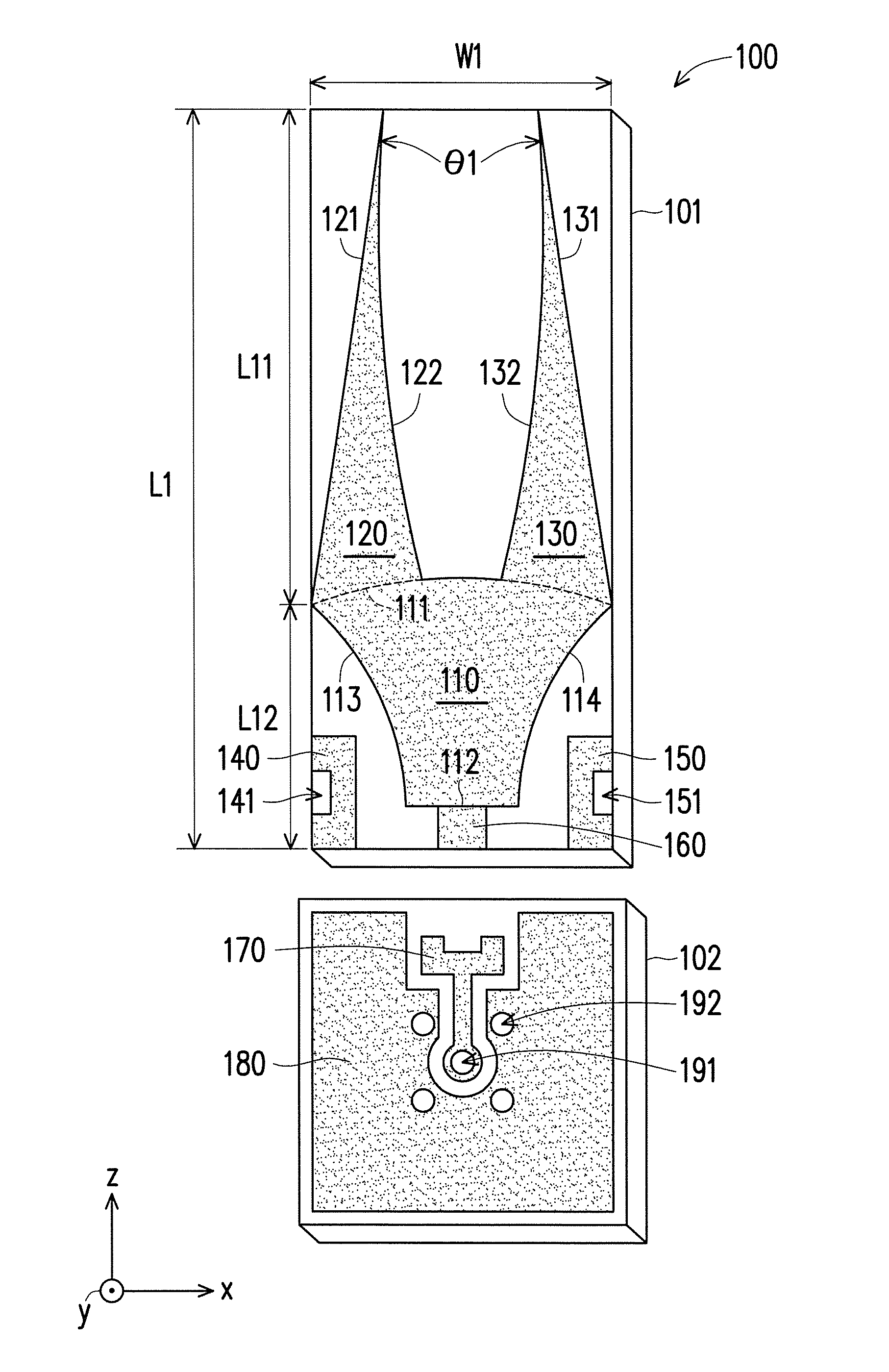
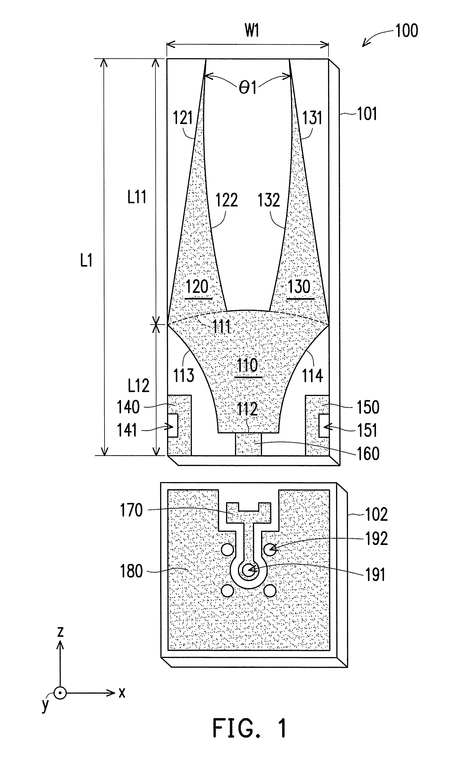
[0018]FIG. 1 is a schematic diagram illustrating a structure of a wideband antenna according to an exemplary embodiment. As shown in FIG. 1, the wideband antenna 100 includes a radiation element 110, a first extension element 120, a second extension element 130, a first reflection element 140, a second reflection elements 150, and a feeding element 160, wherein the radiation element 110 is symmetric to a reference direction, for example, the z-axis direction. The radiation element 110 has a top edge 111, a bottom edge 112, a first side edge 113, and a second side edge 114.

[0019]The top edge 111 of the radiation element 110 is opposite to the bottom edge 112, and the first side edge 113 of the radiation element 110 is opposite to the second side edge 114. In addition, the first side edge 113 and the second side edge 114 define the width of the radiation element 110. For example, plural distances between the first side edge 113 and the second side edge 114 in the z-axis direction defi...


PUM


Abstract

A wideband antenna includes a radiation element, first and second extension elements, first and second reflection elements, and a feeding element. The radiation element is symmetric to a reference direction and has a top edge, a bottom edge, a first side edge, and a second side edge. A width of the radiation element gradually increases along the reference direction. The first and second extension elements are extended toward the reference direction respectively from two ends of the top edge and are mirror-symmetric to each other with respect to the reference direction. Widths of the first and second extension elements gradually decrease along the reference direction. The first and second reflection elements are respectively opposite to the first and second side edges and are mirror-symmetric to each other with respect to the reference direction. The feeding element is electrically connected to the bottom edge and has a feeding point.

Description

CROSS-REFERENCE TO RELATED APPLICATION[0001]This application claims the priority benefit of Taiwan application serial no. 103100056, filed on Jan. 2, 2014. The entirety of the above-mentioned patent application is hereby incorporated by reference herein and made a part of this specification.BACKGROUND OF THE INVENTION[0002]1. Field of the Invention[0003]The invention relates to an antenna and more particularly to a wideband antenna.[0004]2. Description of Related Art[0005]With the development of mobile communication devices with multi-functions and characterized by miniaturization, a newly developed antenna (i.e., antenna under test, AUT) must pass verification tests and product certification tests in a short-range test environment, so as to ensure that the radiation pattern of the antenna meets the application requirements of the mobile communication devices. The AUT is placed in a small shield room in the short-range test environment, and a calibration antenna in the shield room i...

Claims


Application Information

Patent Timeline
Patent Type & Authority Patents(United States)
IPC IPC(8): H01Q13/10H01Q11/06H01Q19/185
CPCH01Q19/185H01Q11/06
Inventor CHOU, CHEN-YU
Owner WISTRON CORP
Learn More