Combine harvester with variable stroke cleaning shoe
- Summary
- Abstract
- Description
- Claims
- Application Information
AI Technical Summary
Benefits of technology
Problems solved by technology
Method used
Image

Examples
first embodiment
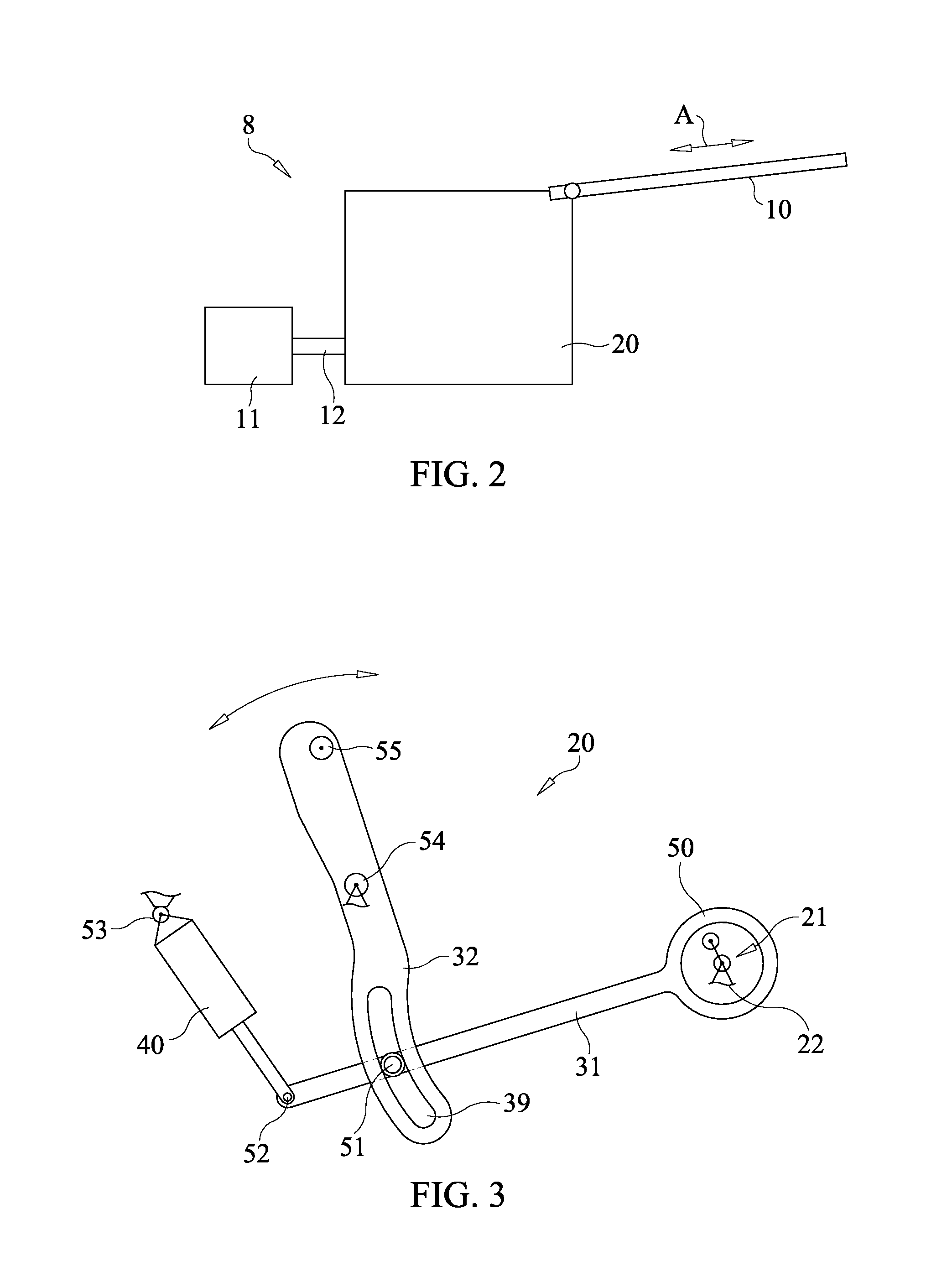
[0065]By changing the rotational speed of the rotatable output shaft 12 of the rotary drive 11, the sieve frequency of the reciprocating sieve movement can be changed. FIG. 3 shows a transmission 20 of a sieve drive assembly according to the invention. In this embodiment, the transmission 20 comprises a single adjustable transmission element. There is no adjustable eccentric device; in this embodiment, the eccentric device has a fixed eccentricity.
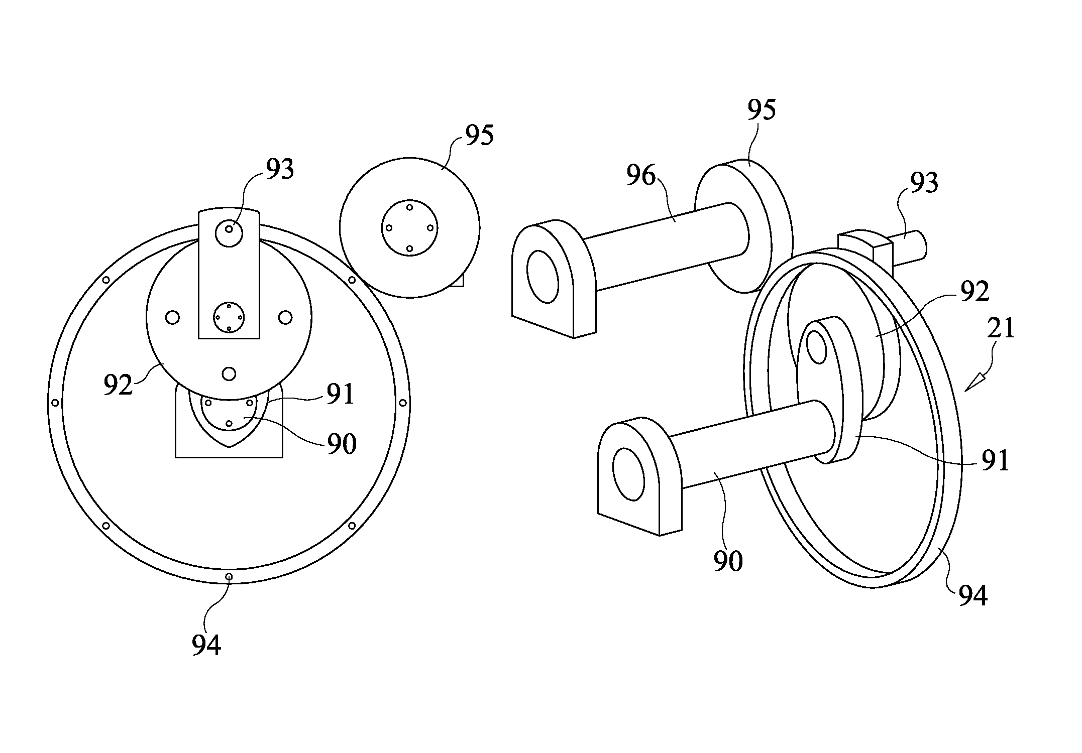
[0066]The transmission 20 of FIG. 3 comprises an eccentric device 21, which is a non-adjustable eccentric device. The eccentric device has an eccentric disk 22 that is connected to the rotatable output shaft of the rotary drive (not shown in FIG. 3) in a fixed way, causing the eccentric disk 22 to rotate along with the rotatable output shaft, for example as indicated by the arrow. The eccentric disk 22 is connected to the rotatable output shaft of the rotary drive at a location away from the center of the eccentric disk 22.
[0067]The transm...
second embodiment
[0076]FIG. 4 shows a transmission 20 of a sieve drive assembly according to the invention. In this embodiment, the transmission 20 comprises a single adjustable transmission element. There is no adjustable eccentric device; in this embodiment the eccentric device has a fixed eccentricity.
[0077]The transmission 20 of FIG. 4 comprises an eccentric device 21, which is a non-adjustable eccentric device. The eccentric device has an eccentric disk 22 that is connected to the rotatable output shaft of the rotary drive (not shown in FIG. 4) in a fixed way, causing the eccentric disk 22 to rotate along with the rotatable output shaft, for example as indicated by the arrow. The eccentric disk 22 is connected to the rotatable output shaft of the rotary drive at a location away from the center of the eccentric disk 22.
[0078]The transmission 20 further comprises four transmission elements 31, 32, 33, 40. One transmission element is an adjustable transmission element 40.
[0079]The transmission 20 ...
third embodiment
[0086]FIG. 5 shows a transmission 20 of a sieve drive assembly according to the invention. In this embodiment, the transmission 20 comprises an adjustable transmission element. There is no adjustable eccentric device; the eccentric device has a fixed eccentricity.
[0087]The transmission 20 of FIG. 5 comprises an eccentric device 21, which is a non-adjustable eccentric device. The eccentric device has an eccentric disk 22 that is connected to the rotatable output shaft of the rotary drive (not shown in FIG. 4) in a fixed way, causing the eccentric disk 22 to rotate along with the rotatable output shaft, for example as indicated by the arrow. The eccentric disk 22 is connected to the rotatable output shaft of the rotary drive at a location away from the center of the eccentric disk 22.
[0088]In the embodiment of FIG. 5, the transmission 20 comprises an adjustable transmission element 40. In this embodiment, the adjustable transmission element 40 is formed by an actuator, for example a h...
PUM
 Abstract
Description
Claims
Application Information
 - R&D
- Intellectual Property
- Life Sciences
- Materials
- Tech Scout
- Unparalleled Data Quality
- Higher Quality Content
- 60% Fewer Hallucinations
Browse by: Latest US Patents, China's latest patents, Technical Efficacy Thesaurus, Application Domain, Technology Topic, Popular Technical Reports.
© 2025 PatSnap. All rights reserved.Legal|Privacy policy|Modern Slavery Act Transparency Statement|Sitemap|About US| Contact US: help@patsnap.com