
Chemical reactor with knitted wire mesh fabric as a holding device for particles

a technology of holding device and wire mesh fabric, which is applied in the manufacture of final products, knitting, physical/chemical process catalysts, etc., can solve the problems of low maintenance cost, difficult to manufacture exactly circular large reactors, and loss of catalysts. , to achieve the effect of low maintenance cos

Active Publication Date: 2016-06-14
COVESTRO DEUTSCHLAND AG
View PDF14 Cites 8 Cited by
  • Summary
  • Abstract
  • Description
  • Claims
  • Application Information

AI Technical Summary

Benefits of technology

The invention provides a reactor that prevents the catalyst from flowing back into the support structure, even if the temperature changes repeatedly. This is done by using an inexpensive and easy-to-maintenance support structure that allows for easy filling with bulk catalyst.

Problems solved by technology

Due to the periodic operation of the reactors, the screen is subjected to thermal stresses which lead to damage.
In these cases deformations in the V-shaped wires originally arranged in parallel can already occur after a few production cycles, up to breaking off or tearing of individual wires.
The repair of a screen damaged in this way requires outlay and does not bring about permanent success.
Furthermore, it is difficult to manufacture exactly circular large reactors.
As a consequence of these problems, a loss of catalyst often occurs in the form of the catalyst trickling through damaged areas of the slotted screen or through openings between the slotted screen and reactor wall or support ring.
The catalyst which has migrated to the reverse of the slotted screen can furthermore cause damage to the apparatuses downstream of it.
Disadvantages of this solution are on the one hand that a not inconsiderable part of the reactor is filled with inert material and is no longer available for the actual catalyst, and on the other hand that the introduction of the various layers into the reactor requires outlay.

Method used


Image

  • Chemical reactor with knitted wire mesh fabric as a holding device for particles
  • Chemical reactor with knitted wire mesh fabric as a holding device for particles
  • Chemical reactor with knitted wire mesh fabric as a holding device for particles

Examples


example e-1

According to the Invention

Slotted Screen, Knitted Wire Fabric, Inert Material, Catalyst

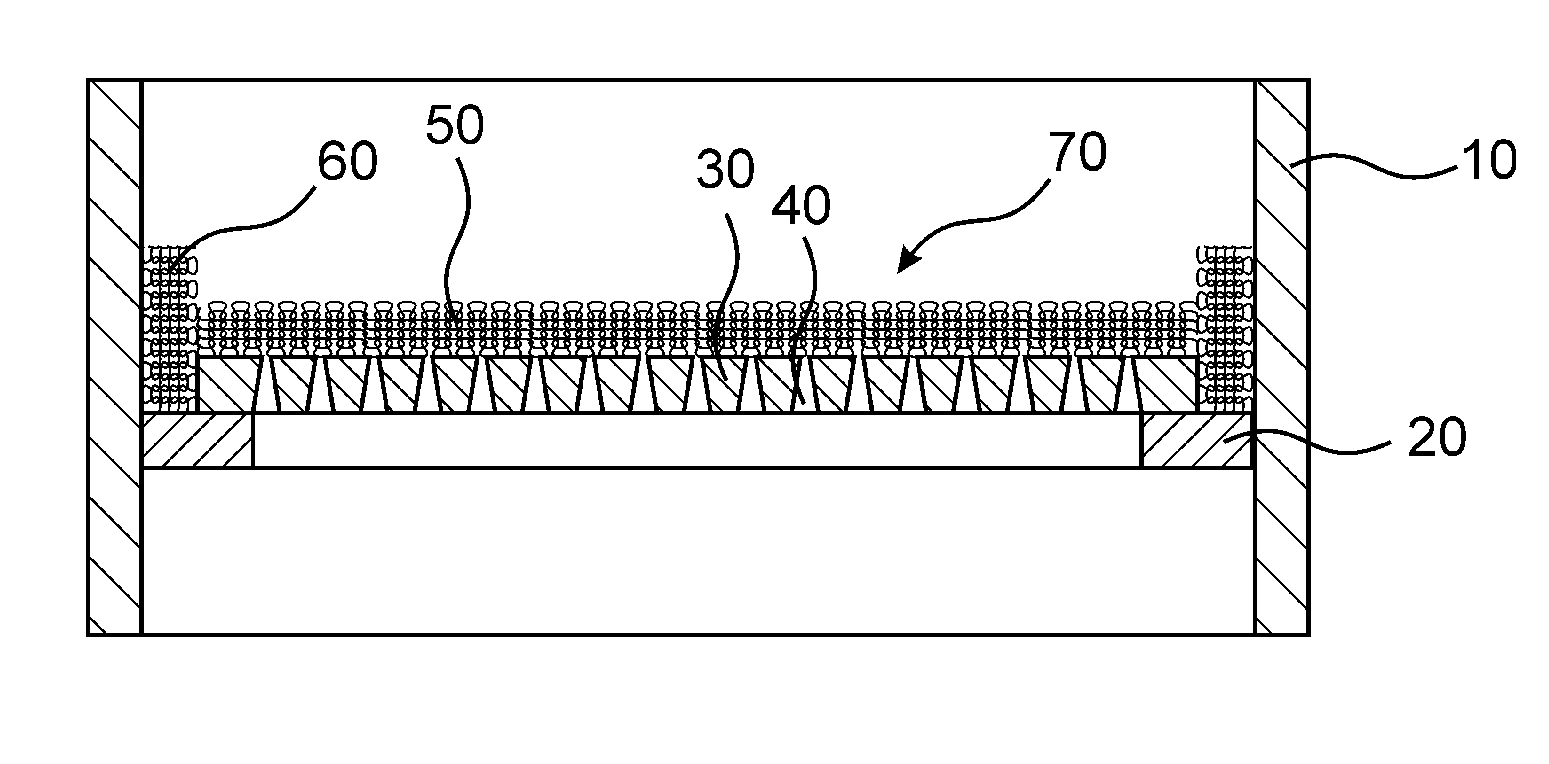
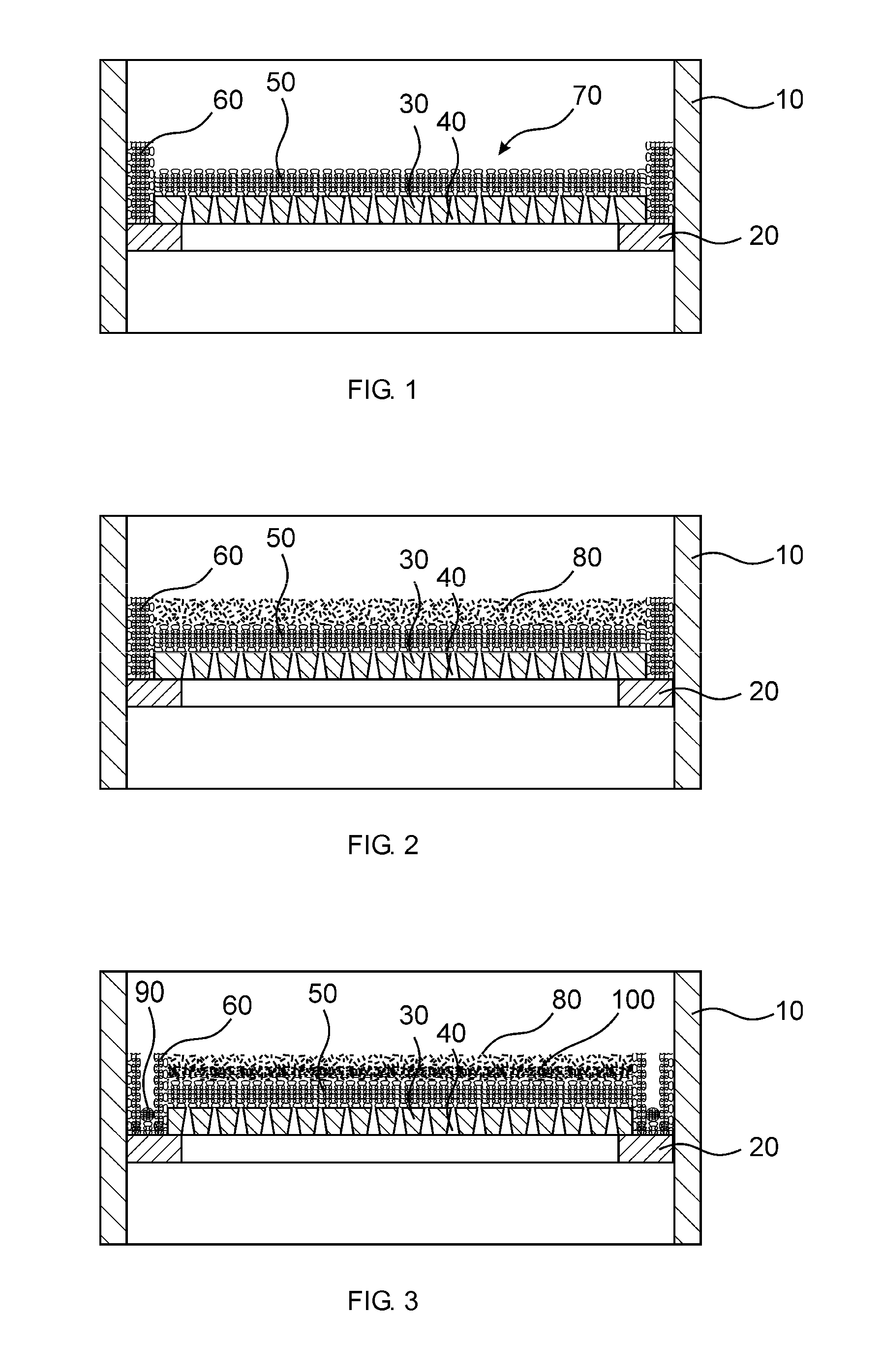
[0081]The experimental procedure corresponded to that of Comparison Example C-1, the slotted screen additionally being covered with a knitted wire mesh fabric of continuous wire. The mesh fabric had a wire diameter of 0.23 mm, was double-knitted and folded in three layers. The mesh fabric was produced from high-grade steel and the average clear mesh width was 0.65 mm. The mesh fabric was fixed to the slotted screen by means of bolts.

[0082]The mesh fabric was covered with a 5 cm high layer of inert material of aluminium oxide beads, which had an average particle size x50.3 of 4 mm.

[0083]The catalyst fixed bed, the catalyst particles of which had an average particle size x50.3 of 1.5 mm, came to lie on the inert material.

[0084]In the test cycle, nitrobenzene was found with a concentration of more than 500 ppm in the reaction product after approx. 38 days. On inspection of the reactor, no thrombi wer...

example e-2

According to the Invention

Slotted Screen, Knitted Wire Fabric, Inert Material, Met. Gasket, Cat.

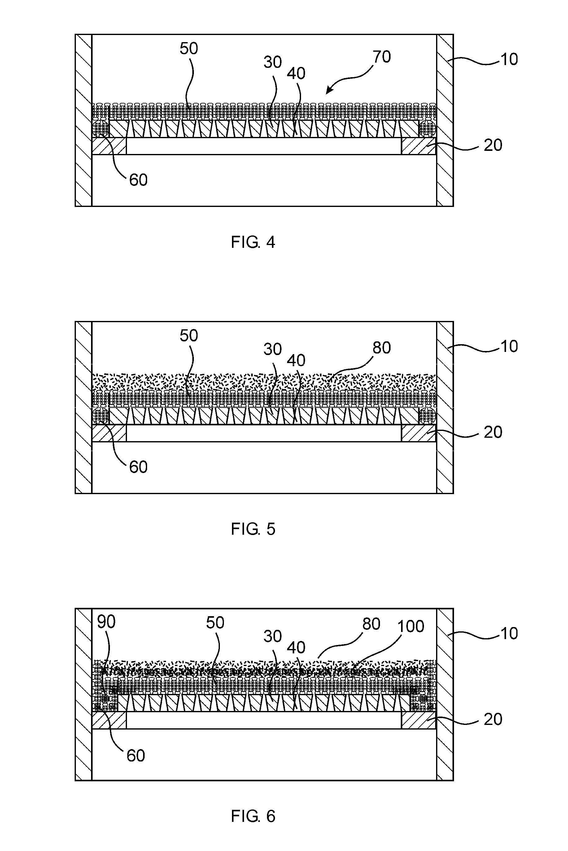
[0085]The experimental procedure corresponded to Example E-1, a metallic gasket of knitted wire mesh fabric, the wire diameter of which was 0.23 mm and the average clear mesh width of which was 0.65 mm, additionally being laid in the gap between the outer support ring of the slotted screen and the reactor wall. The gasket was still flexible even under the reaction conditions and had a diameter of 1.2 cm, so that it was fixed in the gap by its own spring tension.

[0086]In the test cycle, nitrobenzene was found with a concentration of more than 500 ppm in the reaction product after approx. 38 days. On inspection of the reactor, no thrombi were found in the catalyst bed, although damage was again observed on the supporting screen. The catalyst bed showed no depression along the reactor wall. Neither catalyst nor inert material was found on the reactor base and in the downstream apparatuses.

example e-3

According to the Invention

Simple Grating, Knitted Wire Fabric, Metallic Gasket, Catalyst

[0087]In this example, an adiabatic hydrogenation of nitrobenzene to give aniline was carried out in a reactor which was equipped with a simple grating for the catalyst bed. The average mesh width of the grating was 30×10 mm. Corrosion and bending of the profiles and supporting profiles were prevented by using austenitic steel. The outer support ring of the grating was mounted in a floating manner on a bearing ring on the reactor wall. In the cold state, there was thereby a gap of approx. 1 cm between the support ring and the reactor wall. A metallic gasket of knitted wire mesh fabric, the wire diameter of which was 0.23 mm and the average clear mesh width of which was 0.65 mm, was laid in this gap. The gasket was still flexible even under the reaction conditions and had a diameter of 1.2 cm, so that it was fixed in the gap by its own spring tension.

[0088]The grating was covered with a knitted wi...


PUM

PropertyMeasurementUnit
diameteraaaaaaaaaa
heightaaaaaaaaaa
temperatureaaaaaaaaaa

Abstract

In a chemical reactor for heterogeneously catalyzed reaction of a fluid, comprising a holding device for catalyst particles and / or inert particles (80, 100) through which the fluid flows, the side of the holding device lying upstream when viewed in the direction of flow of the fluid comprises knitted wire mesh fabric (50), and the average clear mesh width of the knitted wire fabric (50) is smaller than the average particle size x50.3 of the particles (80, 100). The invention furthermore relates to a process for reaction of a fluid, wherein the reaction is carried out in a reactor according to the invention in the presence of heterogeneous catalyst particles (80) and the catalyst particles (80) are arranged in the holding device for catalyst particles (80). The invention also provides the use of knitted wire mesh fabric (50) as a holding device for catalyst particles and / or inert particles (80, 100) in chemical reactors.

Description

CROSS REFERENCE TO RELATED APPLICATIONS[0001]This application is a §371 National Stage Application of PCT / EP2011 / 070101, filed Nov. 15, 2011, which claims priority to German Application No. 10 2010 044 111.2; filed Nov. 18, 2010.BACKGROUND OF THE INVENTION[0002]1. Field of the Invention[0003]The present invention relates to a chemical reactor for heterogeneously catalysed reaction of a fluid with an improved holding device for inert particles and / or catalyst particles through which the fluid flows. It furthermore relates to a process for carrying out chemical reactions by means of such a reactor and to the use of knitted wire mesh fabric in chemical reactors.[0004]2. Description of Related Art[0005]The hydrogenation of nitroaromatics to give the corresponding amines in a fixed bed reactor with axial flow can be carried out in a multi-stage process under adiabatic reaction conditions. Such hydrogenations proceed in periodic cycles, production cycles alternating with regeneration cycl...

Claims


Application Information

Patent Timeline
Patent Type & Authority Patents(United States)
IPC IPC(8): B01J8/02C07C209/00B01J8/44
CPCB01J8/025B01J8/44B01J8/0292B01J2208/00884Y10T428/12424B01J8/008B01J8/0242C07C209/36C07C211/46D04B1/14Y02P70/62B01J8/02
Inventor MERKEL, MICHAELWILKE, KARL-HEINZKNAUF, THOMAS
Owner COVESTRO DEUTSCHLAND AG
Learn More