Hydraulic shimmy damper for aircraft landing gear

a technology of aircraft landing gear and damper, which is applied in the direction of shock absorbers, machine supports, transportation and packaging, etc., can solve the problems of reducing damping capacity and compromising gear stability, and achieve the effect of easy tuning

Active Publication Date: 2016-05-31
SAFRAN LANDING SYST CANADA INC
View PDF14 Cites 1 Cited by
  • Summary
  • Abstract
  • Description
  • Claims
  • Application Information

AI Technical Summary

Benefits of technology

[0011]An object of the invention is to provide a shimmy damper that is cavitation free, offering damping characteristics depending very little on oil temperature, and easy to tune.BRIEF DESCRIPTION OF THE INVENTION
[0017]a hydraulic manifold arranged between said body and said hydraulic compensator and defining a transfer channel between said chambers that is connected to said hydraulic compensator and further receiving interchangeable hydraulic cartridge-type valves for metering the fluid flowing from said chambers to said transfer channel, and allowing the fluid to freely enter said chambers from said transfer channel.Said hydraulic cartridge-type valves have internal screens to protect them from big particle contaminants.
[0018]Thanks to the important volume of the compensator, the metered fluid expelled from the body generates only marginal temperature elevation of the total oil volume contained within the shimmy damper. This makes the shimmy damper of the invention much less sensitive to oil temperature variation under intense shimmy.
[0019]Furthermore, the use of standard hydraulic cartridge-type valves makes it easy to change said valves to tune the metering characteristics of the shimmy damper. The shimmy damper of the invention can be very easily adapted to various landing gears, and may be modified during the life of the landing gear to account for shimmy characteristics changes of the landing gear due to ageing and wear.

Problems solved by technology

Shimmy is a complex oscillatory phenomenon affecting some aircraft landing gears to such a level that the gear stability may be jeopardized.
Those shimmy dampers were thought to suffer from at least one of the following drawbacks:very low damping coefficient, based on small hydraulic restrictions, because incorporation of higher restrictions would have required to protect the restricted orifice by a screen, which may be difficult to integrate in the known designs;the hydraulic restriction suffers from important geometric tolerance, because it is often provided with simple drilled holes as opposed to a precise calibrated hole;the hydraulic restriction suffers from important oil temperature variations;the anti-cavitation valves are often custom made, which make them hard to change if a high frequency response is required after tests;the hydraulic chamber oil volume is small, and the oil quickly gets heated under intense shimmy, diminishing the damping capacity.the hydraulic compensator is threaded into shimmy damper body, making a weak mechanical connection that may fail under vibration fatigue, like in previous incidents.

Method used


Image

  • Hydraulic shimmy damper for aircraft landing gear
  • Hydraulic shimmy damper for aircraft landing gear
  • Hydraulic shimmy damper for aircraft landing gear

Examples


Embodiment Construction

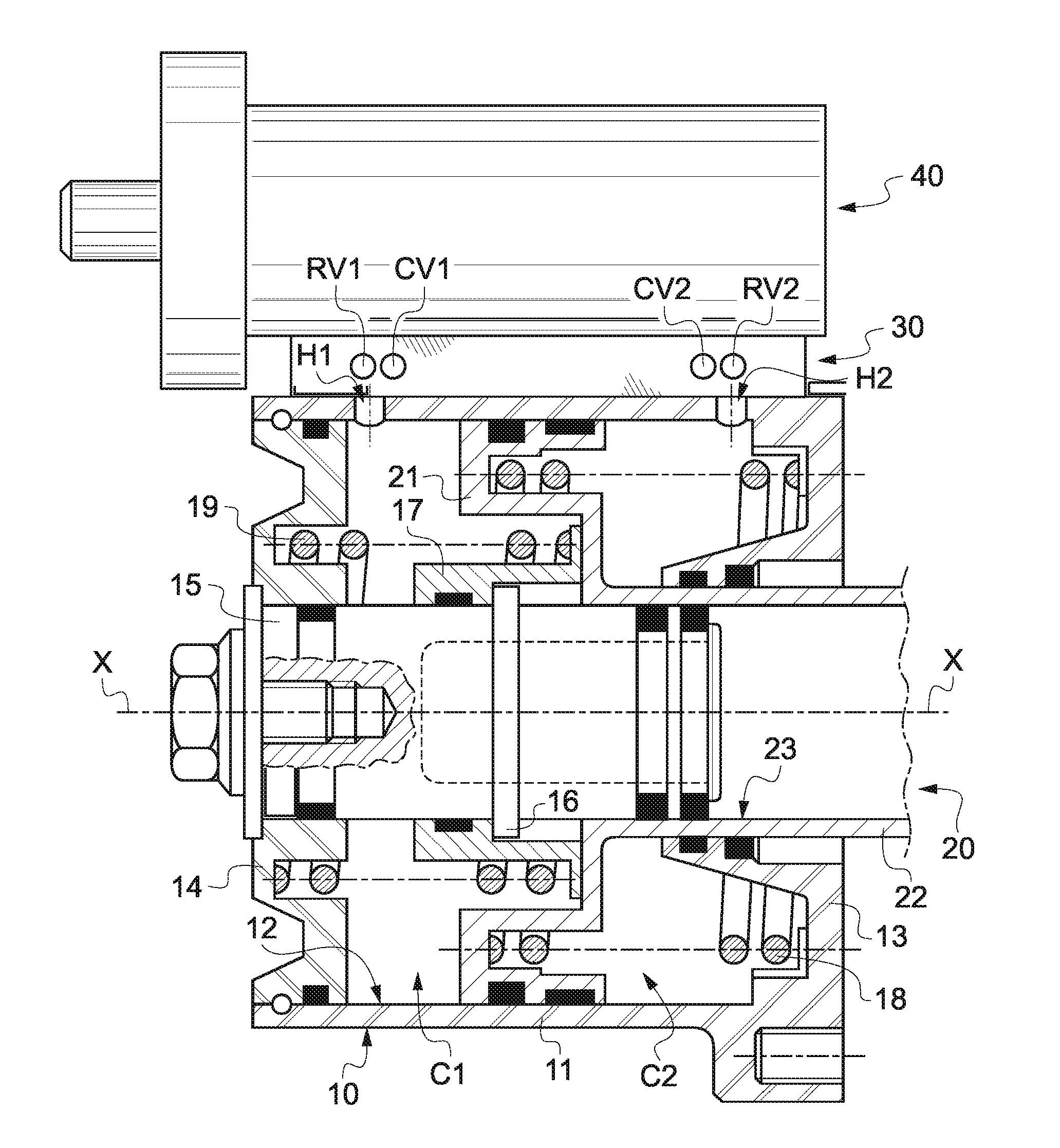
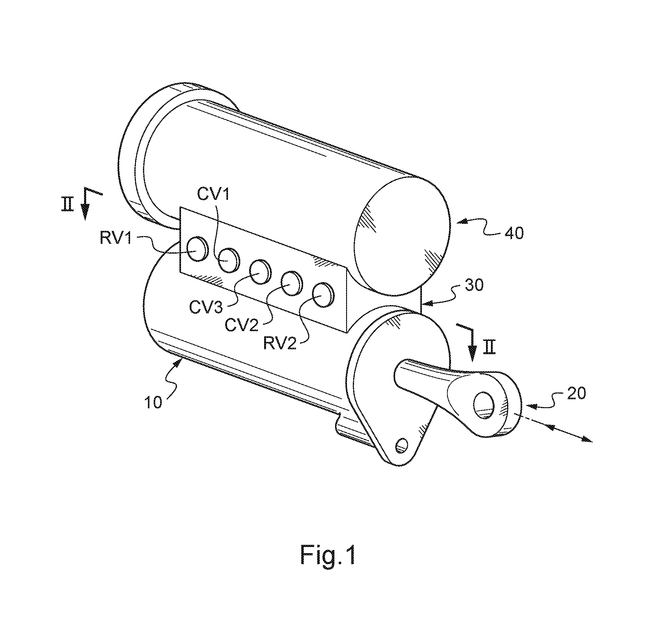
[0024]With reference to FIG. 1, the hydraulic shimmy damper comprises a body 10 in which a piston 20 is engaged for translational motion along a longitudinal axis X. Said body 10 is attached to a hydraulic manifold 30, which in turn is attached to a hydraulic compensator 40. The shimmy damper is to be installed at a joint between two relatively oscillating components of the landing gear, one component being affixed to said body 10 while the other component is affixed to said piston 20. As an example, the shimmy damper may be installed between the torque links extending between the gear cylinder and the gear piston.

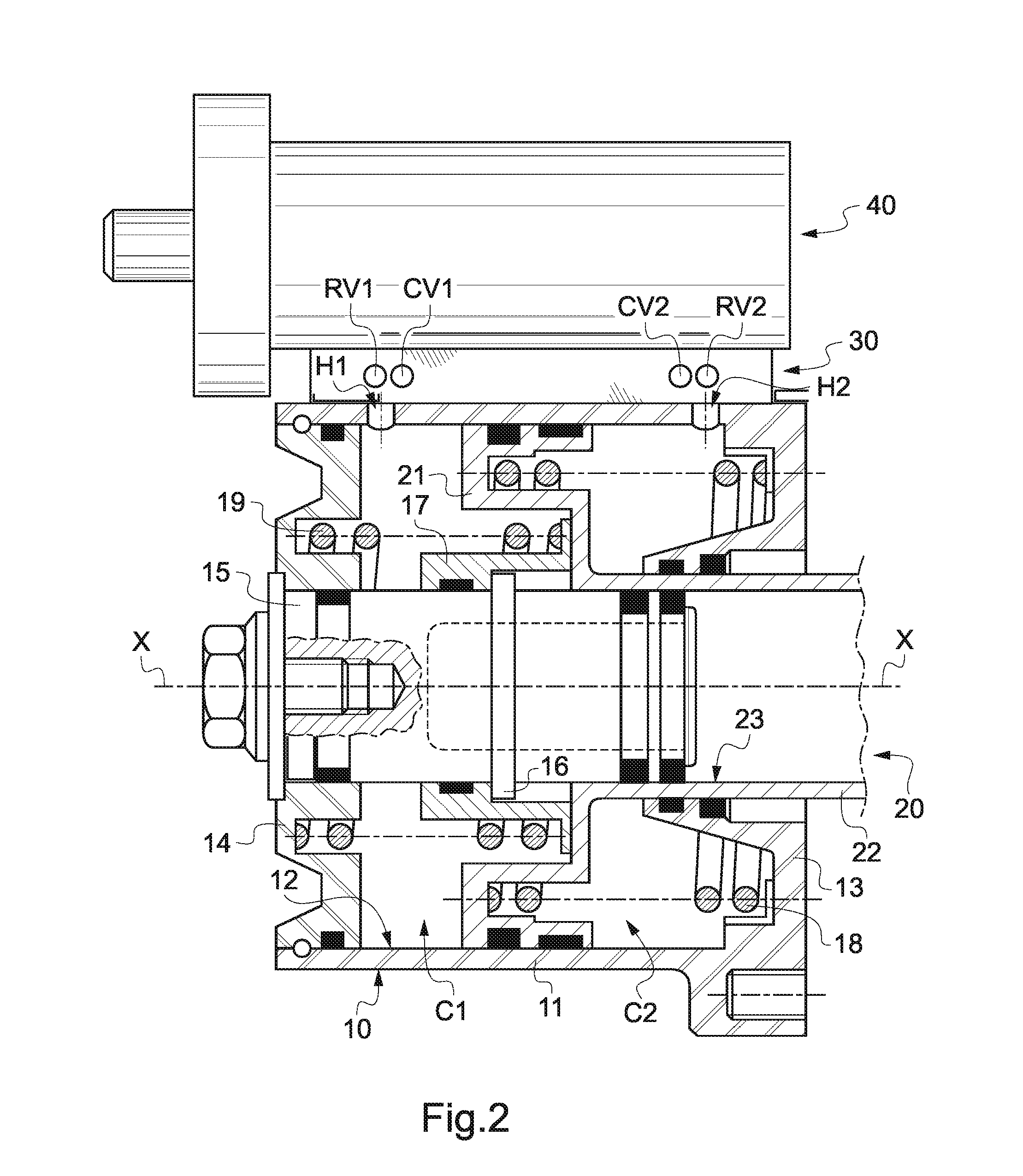
[0025]With reference to FIG. 2, said body 10 comprises a hollow cylinder 11 having an inner cylindrical surface 12 and a first end wall 13. Said cylinder 11 is closed at the opposite side thereof by a second end wall 14 so as to define an internal functional volume. Said piston 20 has a piston head 21 that sealingly engages said inner cylindrical surface 12 to define two h...


PUM


Abstract

A hydraulic shimmy damper that resolves drawbacks in several known shimmy dampers, such as damping characteristics that are dependent on oil temperature variations. The disclosed shimmy damper includes a hydraulic compensator (40) having an internal fluid volume that is significantly more important than a fluid volume expelled from the body of the shimmy damper when its piston moves fore and aft. The shimmy damper also includes a hydraulic manifold (30) arranged between the body and the hydraulic compensator and defining a transfer channel between chambers in the piston that is connected to the hydraulic compensator. The manifold receives interchangeable hydraulic cartridge-type valves (CV1,RV1; CV2,RV2) for metering the fluid flowing from the chambers to the transfer channel, and allows the fluid to freely enter the chambers from the transfer channel. The present shimmy damper is therefore much less sensitive to oil temperature variation under intense shimmy.

Description

CROSS REFERENCE TO RELATED APPLICATIONS[0001]This application is a National Stage of International Application No. PCT / CA2011 / 050464 filed Jul. 28, 2011, claiming priority based on Canadian Patent Application No. 2 711 199 filed Jul. 29, 2010, the contents of all of which are incorporated herein by reference in their entirety.[0002]This invention relates to shimmy dampers, in particular those shimmy dampers used on aircraft landing gears to damp gear vibrations.PRIOR ART[0003]Shimmy is a complex oscillatory phenomenon affecting some aircraft landing gears to such a level that the gear stability may be jeopardized. It has been a long aeronautic industry practice to equip landing gears with shimmy dampers to prevent vibrations evolving in a divergent way. Such a shimmy damper is illustrated in U.S. Pat. No. 5,224,668.[0004]In several aircraft incidents, some very known shimmy dampers have been identified as unable to damp shimmy phenomenon. Those shimmy dampers were thought to suffer ...

Claims


Application Information

Patent Timeline
Patent Type & Authority Patents(United States)
IPC IPC(8): B64C25/50F16F9/06F16F9/32F16F13/00
CPCB64C25/505F16F9/065F16F9/325F16F13/007
Inventor BESLIU, MARIN
Owner SAFRAN LANDING SYST CANADA INC
Why Eureka
Try Eureka