
Vertical lift walker for sit to stand transition assistance

a vertical lift and walker technology, applied in the direction of walking sticks, wheelchairs/patient conveyances, transportation and packaging, etc., can solve the problems of increased weight, inconvenience, additional weight, and inconvenient use of such springs for lift assist operation, so as to avoid frontward stoppage, reduce the cost, and facilitate assembly and disassembly. rapid and easy

Active Publication Date: 2016-05-31
U S GOVERNMENT REPRESENTED BY THE DEPT OF VETERANS AFFAIRS +1
View PDF14 Cites 14 Cited by
  • Summary
  • Abstract
  • Description
  • Claims
  • Application Information

AI Technical Summary

Benefits of technology

The lift walker is a versatile and lightweight device that can help individuals stand and be transferred to different positions. It has a unique structure and does not require the use of handles or retention harnesses. It uses coordinated gas springs which create a balanced and vertical motion, even when under heavy strain. The force output of the lift walker can be customized for users of different weights or sizes. Additionally, it has anti-tip features to prevent the unit and user from tilting over frontward.

Problems solved by technology

Use of such springs for the lift assist operation is less desirable because such approaches do not offer a constant force output through the entire range of motion, a feature that is important for the stable lift assist operation of a vertical platform.
This is disadvantageous for two reasons.
First, the cylinder line of action changes as the platform rotates around the pivot point, resulting in a variable vertical force supplied to the user.
Second, the rotary motion moves the platform forward, away from the user, as it moves upward.
In some cases, known walkers attempt to provide vertical platform motion something which requires a battery, electric motors and belts or straps to be used during operation, which itself offers the additional disadvantage of recharging, added weight, discomfort, inconvenience and the like.

Method used


Image

  • Vertical lift walker for sit to stand transition assistance
  • Vertical lift walker for sit to stand transition assistance
  • Vertical lift walker for sit to stand transition assistance

Examples


Embodiment Construction

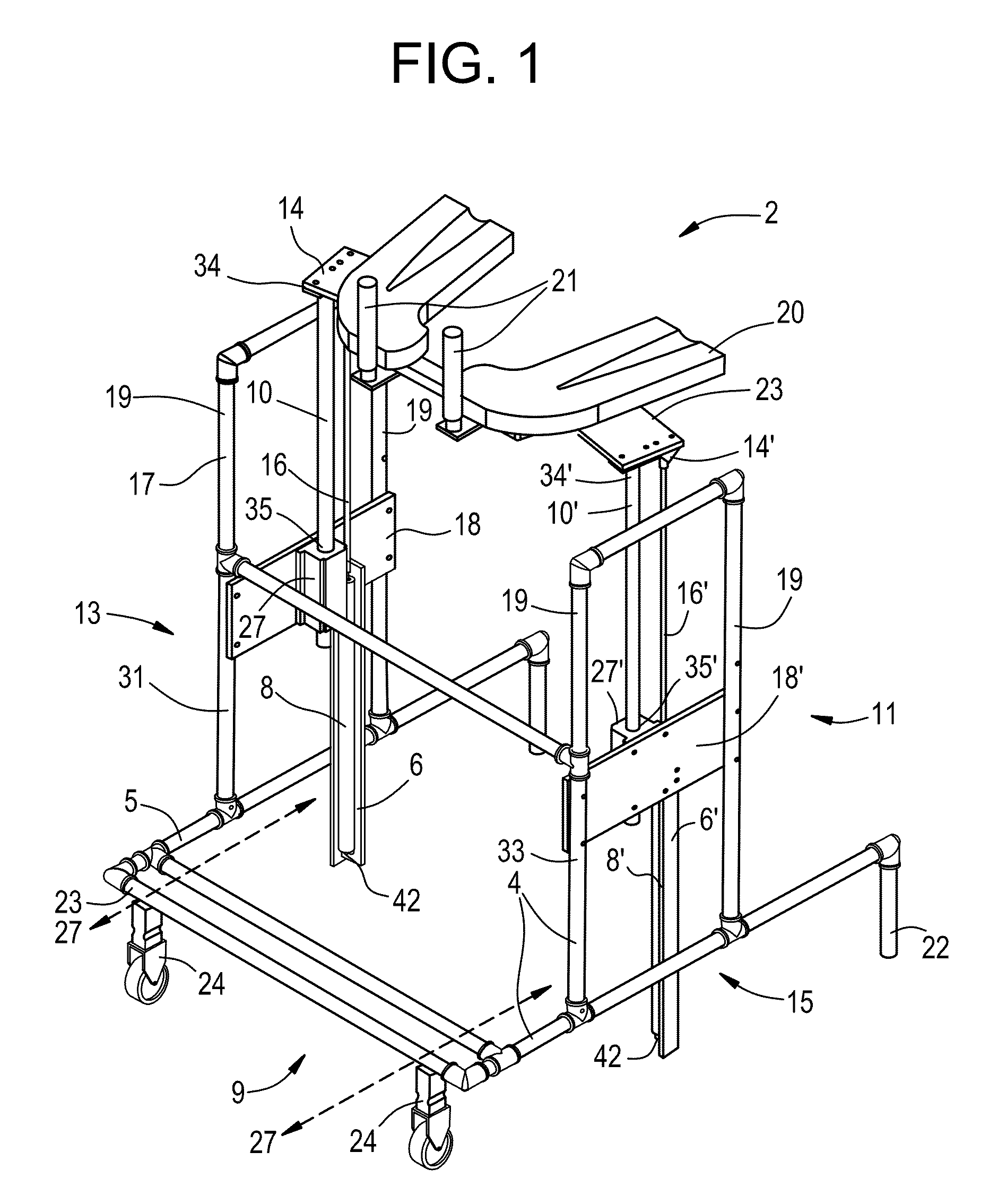
[0018]At its broadest level, the present invention relates to a lift walker comprising: a frame assembly having: a lower frame assembly adapted to contact the ground; an upper frame assembly vertically affixed to the lower frame assembly; the upper frame assembly comprising a plurality of uprights mounted to the lower frame assembly, a bracing assembly and an elevator assembly. The plurality of uprights comprises at least one left upright structure and at least one right upright structure. The elevator assembly is mounted via lift brackets and via the stabilization brackets to the plurality of uprights of said upper frame assembly, wherein the elevator assembly comprises at least a left lift and stabilization track and a right lift and stabilization track, or alternatively, might comprise at least one center stabilization track and a left lift track and a right lift track. Note that in either case, and regardless of the respective terminology employed thereof, the “lift” and “stabil...


PUM


Abstract

This invention relates to a lift to assist in standing and / or walking for persons who have insufficient strength or movement in their legs. The inventive lift walker includes a frame assembly having a lower an upper and lower portion that wheels are provided beneath the lower frame so as to enable the lift to be propelled and maneuvered. A bracing assembly is provided at the upper portion and comprises a supporting platform which is adapted to fit under the forearms of a person, and optional handles for gripping by the user's left and right hands. An elevator assembly is provided which includes lift and stabilization tracks for raising and lowering the supporting assembly in a coordinated, purely vertical fashion, and further includes gas lift means for effectuating the same via use of a remotely switched activation mechanism. There are also anti-tip means for maintaining the stability of the device when contacting uneven ground surface during movement.

Description

FIELD OF THE INVENTION[0001]The present invention is related to the field of ambulatory assist devices, that is, lift walkers. Specifically, aspects of the invention provide a lift walker having elevator and bracing assemblies that are adapted to assist the user in rising from a seated position to a standing position or sitting from a standing position. The proposed invention therefore relates to a novel approach to improving an assistive lift walker device for restoration of independent sit-to-stand and walking functions for patients with limited lower extremity strength and motor control. More specifically, the device provides significant body weight support during the sit-to-stand transition and can support, in a stable fashion, nearly full body weight during standing and walking activities.BACKGROUND OF THE INVENTION[0002]Known approaches for lift walkers often incorporate mechanical springs and the like for the lift assist operation. Use of such springs for the lift assist oper...

Claims


Application Information

Patent Timeline
Patent Type & Authority Patents(United States)
IPC IPC(8): A61G5/14A61H3/00A61H3/04A61G7/10
CPCA61H3/00A61G5/14A61H3/04A61G7/1019A61G7/1092A61G7/1094A61H2201/1638
Inventor TRIOLO, RONALD J.BULEA, THOMAS C.
Owner U S GOVERNMENT REPRESENTED BY THE DEPT OF VETERANS AFFAIRS
Learn More