
Unequal rate interference cancellation

Active Publication Date: 2016-05-24
L3 TECH INC
View PDF2 Cites 1 Cited by
  • Summary
  • Abstract
  • Description
  • Claims
  • Application Information

AI Technical Summary

Benefits of technology

The present invention provides systems, methods, and apparatus for removing co-channel interference from received signals transmitted at different rates. This technology is useful in a variety of digital communication fields, including those involving cross-polarization interference and multi-directional signals. It helps to improve the quality of the received signals and reduces interference.

Problems solved by technology

The first composite signal and the second composite signal may share the same frequency band causing co-channel interference; however, the first composite signal and the second composite signal may comprise constituent signals of different chipping or symbol rates.
The first composite signal and the second composite signal may share the same frequency band causing co-channel interference; however, the first composite signal and the second composite signal may comprise different chipping or symbol rates.

Method used


Image

  • Unequal rate interference cancellation
  • Unequal rate interference cancellation
  • Unequal rate interference cancellation

Examples


Embodiment Construction

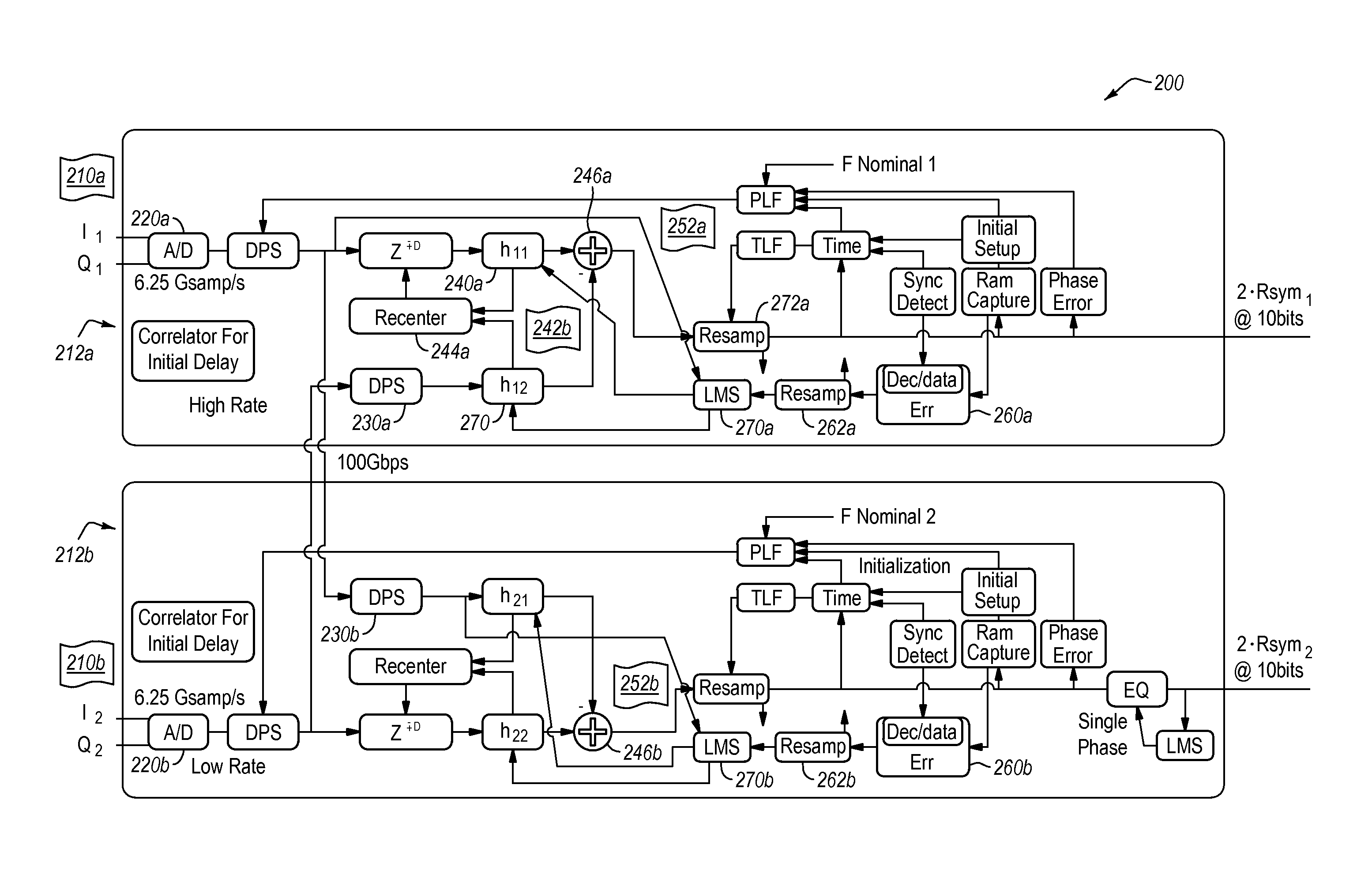
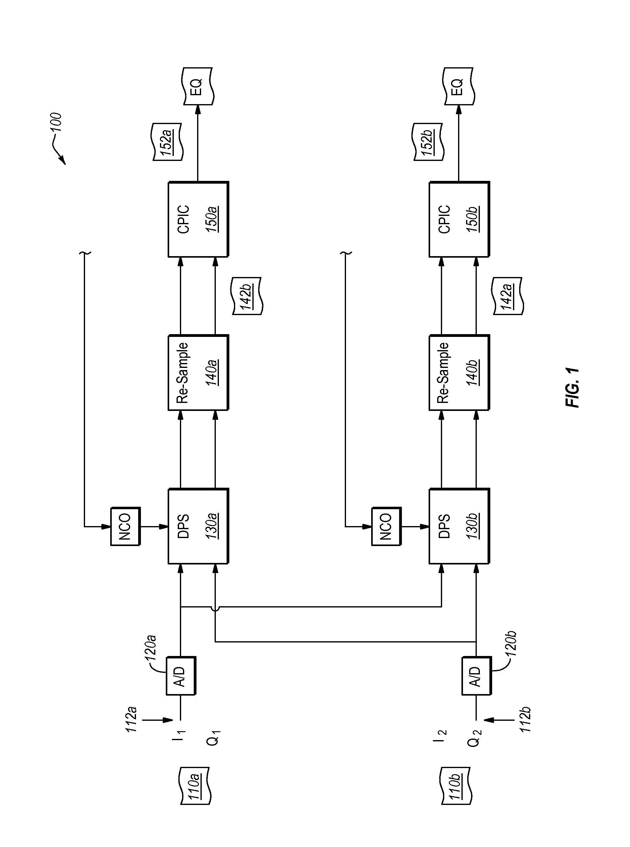
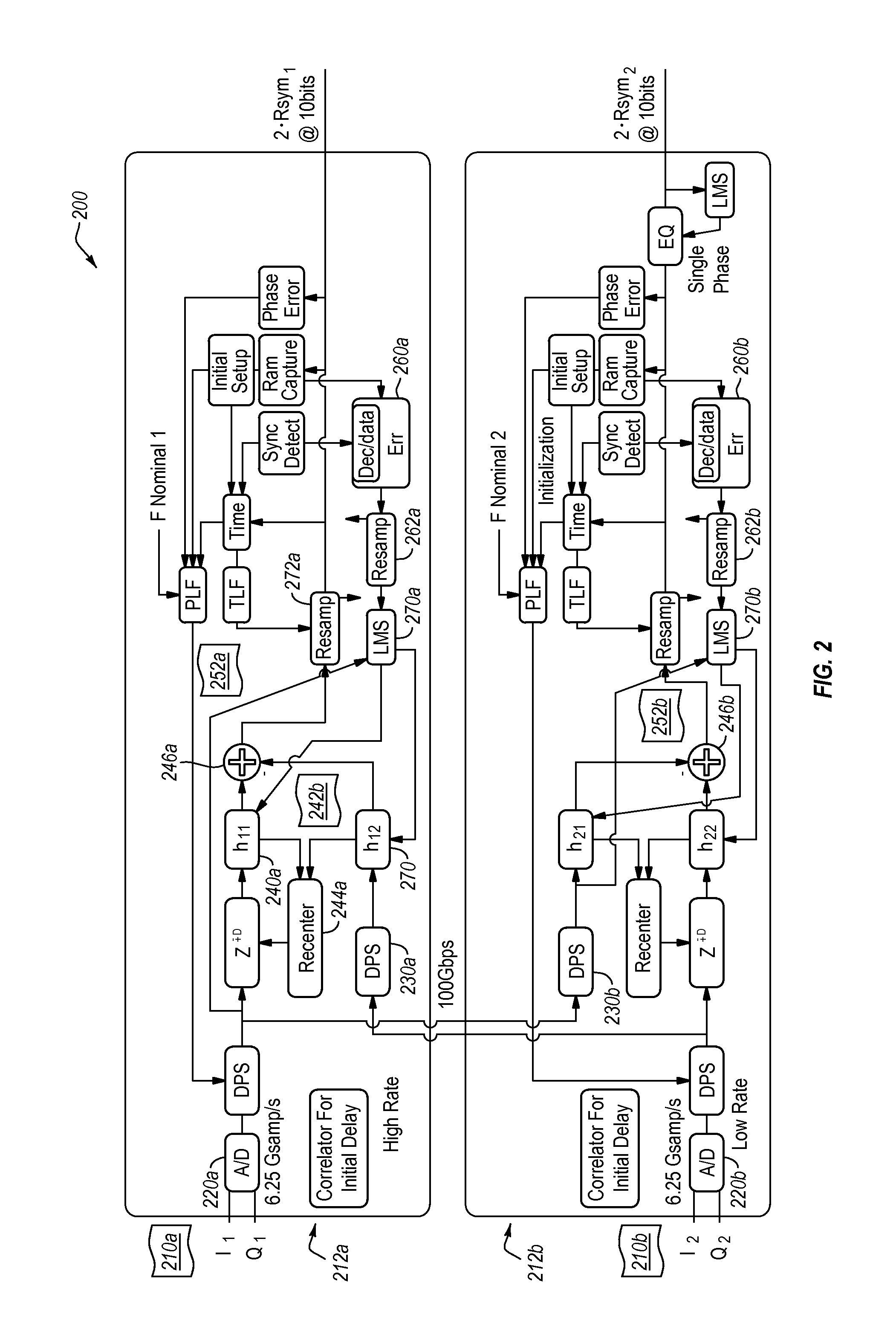
[0022]The present invention extends to systems, methods, and apparatus configured to remove co-channel interference from one or more received signals that comprise different symbol or chipping rates. In particular, implementations of the present invention comprise computer systems, methods, and computer-readable media for receiving one or more co-channel signals transmitted at different rates, identifying co-channel interference caused by at least one of the signals, and removing the identified co-channel interference from the other signal. As such, implementations of the present invention provide significant benefits within multiple digital communication fields, including communication fields that deal with cross-polarization interference, multi-directional signals, and other fields that may experience co-channel interference.

[0023]Accordingly, implementations of the present invention efficiently remove co-channel interference that is at a different symbol rate or chipping rate tha...


PUM


Abstract

A method for receiving and removing co-channel interference from one or more received signals that comprise different symbol or chipping rates can comprise receiving a first composite signal and a second composite signal. The method can also comprise sampling the first composite signal and the second composite signal at a particular sampling rate that is sufficient to recover signal data from both the first composite signal and the second composite signal. Further, the method can comprise estimating from the second composite signal an estimated cross-coupled second signal within the first composite signal. The estimated cross-coupled second signal is estimated from at least the second composite signal at the particular sampling rate. Further still, the method can comprise recovering a substantially decoupled first data signal by removing at least a portion of the co-channel interference caused by the estimated cross-coupled second signal from the composite first signal.

Description

BACKGROUND OF THE INVENTION[0001]1. Technical Field[0002]The present invention relates generally to digital signal processing.[0003]2. Background and Relevant Art[0004]Digital communication and signal processing have become ubiquitous in the modern world. In particular, over-the-air communication via cellular phones, Wi-Fi connections, and other similar communication devices has experienced an explosion in bandwidth requirements and usage in recent years. This increase in bandwidth utilization has resulted in significant innovations within the area of communication technologies.[0005]A variety of different methods are used to optimize bandwidth within particular frequency bands. For example, cross-polarization of signals can be used to effectively double the bandwidth of a particular frequency channel. Cross-polarized signals can be transmitted within the same frequency band, but at distinguishably different polarizations. A receiver can receive both signals within the same frequenc...

Claims


Application Information

Patent Timeline
Patent Type & Authority Patents(United States)
IPC IPC(8): H04L27/06H04B1/10H04L1/00
CPCH04B1/1027H04L1/0091H04B2001/1045H04L1/206H04B1/1036
Inventor LANDON, DAVID G.HADDADIN, OSAMA S.
Owner L3 TECH INC
Learn More