
Auxiliary power unit for emergency light in case of fire or power failure

a technology of auxiliary power units and emergency lights, which is applied in the direction of emergency power supply arrangements, electroluminescent light sources, electric lighting sources, etc., can solve the problems of people in danger of moving, people may not find and it is difficult for people in emergency situations to calmly operate the emergency light lighting switch

Active Publication Date: 2016-05-24
HYUNG JE ELECTRIC +2
View PDF3 Cites 7 Cited by
  • Summary
  • Abstract
  • Description
  • Claims
  • Application Information

AI Technical Summary

Benefits of technology

The patent describes an auxiliary power unit (APU) that can be used in case of a fire or power failure. It can automatically turn on an emergency light to help people escape from a building safely, without the need for a separate switch. This ensures that people in danger can have a safe path to evacuation, even in situations where regular power fails.

Problems solved by technology

Typically, the emergency light is turned on in case of power failure, and induces people in danger to move to a safe path.
In most cases, since a power failure is accompanied when a fire occurs, emergency power is supplied.
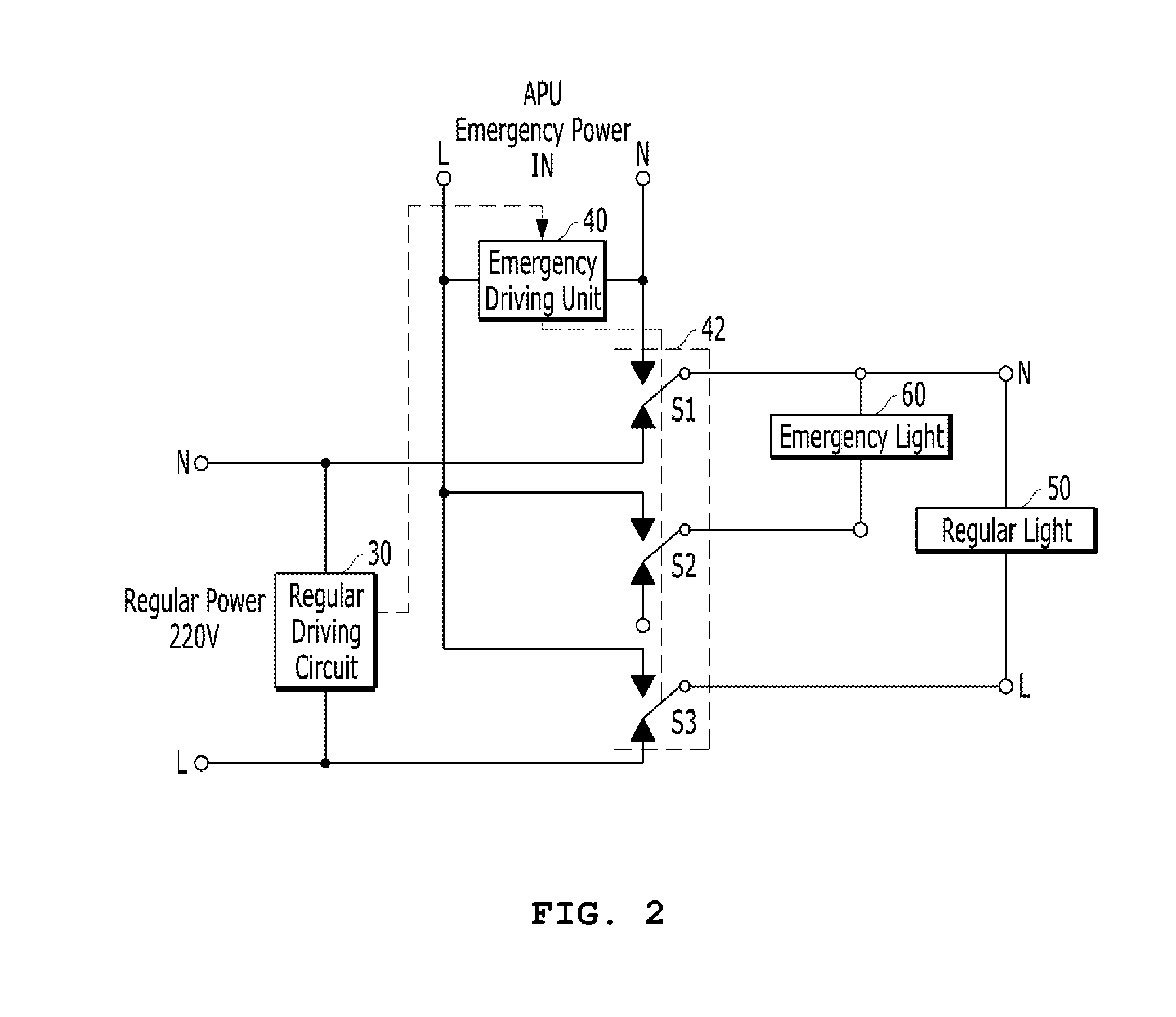
However, since the visual fields of people are hidden by smoke when a fire occurs, the people may not find the lighting switch of the emergency light 60.
Furthermore, it is very difficult for the people in the emergency situation to calmly operate the lighting switch of the emergency light 60.
However, the patent document only discloses the technology which automatically turns on the emergency light in case of a power failure.

Method used


Image

  • Auxiliary power unit for emergency light in case of fire or power failure
  • Auxiliary power unit for emergency light in case of fire or power failure
  • Auxiliary power unit for emergency light in case of fire or power failure

Examples


Embodiment Construction

[0026]Exemplary embodiments will be described below in more detail with reference to the accompanying drawings. The disclosure may, however, be embodied in different forms and should not be constructed as limited to the embodiments set forth herein. Rather, these embodiments are provided so that this disclosure will be thorough and complete, and will fully convey the scope of the disclosure to those skilled in the art. Throughout the disclosure, like reference numerals refer to like parts throughout the various figures and embodiments of the disclosure.

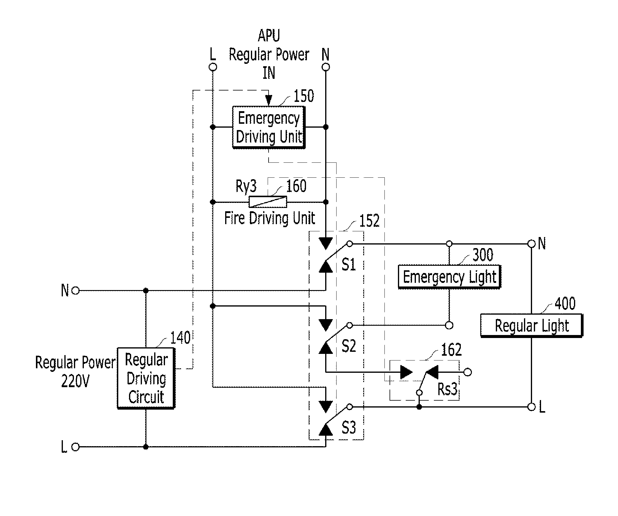
[0027]FIG. 3 illustrates a system which receives emergency power from an ATS (Auto Changeover switch) according to an embodiment of the present invention. FIG. 4 is a system diagram illustrating an APU (Auxiliary Power Unit) according to an embodiment of the present invention.

[0028]The ATS serves to automatically switch over from regular power received from a power supply company to emergency power such as generator power or battery p...


PUM


Abstract

An APU for an emergency light in case of a fire or power failure includes: a regular power input unit; an emergency power input unit; a changeover switch configured to switch the power input such that the emergency light is automatically turned on by the emergency power in case of a power failure of the regular power; a firefighting power monitoring relay operated by firefighting power when a fire occurs; a firefighting-power-monitoring-relay contact switch configured to connect power from an ATS to the emergency power input unit in connection with the firefighting power monitoring relay; a fire driving unit operated by the power inputted to the emergency power input unit; and an emergency light auto lighting switch configured to connect the emergency light to the regular power input unit, such that the emergency light is automatically turned on.

Description

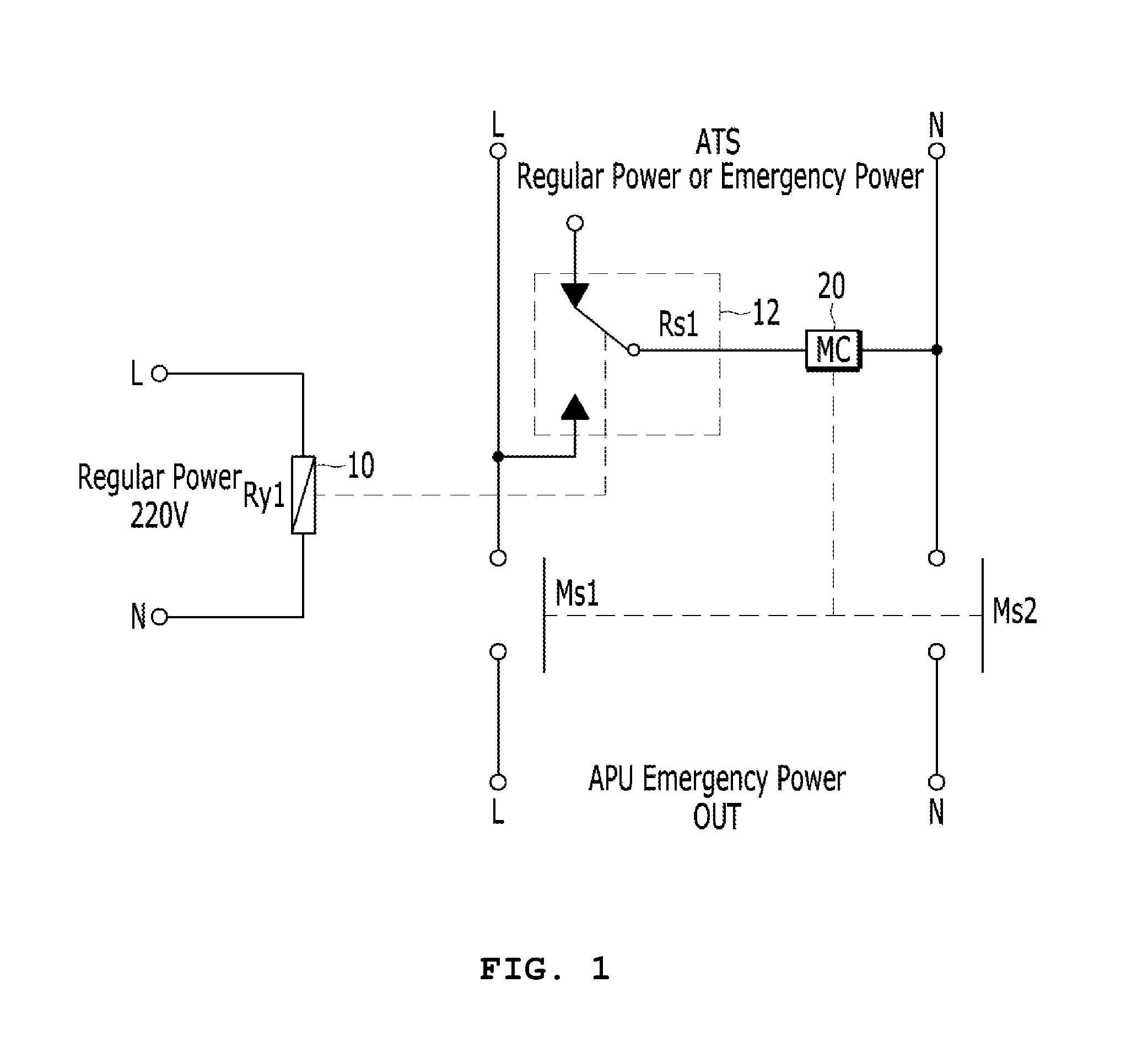
BACKGROUND[0001]1. Technical Field[0002]The present disclosure relates to a unit for supplying power to an emergency light in case of a fire or power failure, and more particularly, to an auxiliary power unit (APU) for an emergency light in case of a fire or power failure, which automatically turns on emergency lights installed at emergency paths and emergency exits when a fire occurs in a live wire state of regular power, such that people in danger can safely escape from the building.[0003]2. Related Art[0004]In general, emergency lights are installed at an emergency path and emergency exit in a building such as an apartment house. Typically, the emergency light is turned on in case of power failure, and induces people in danger to move to a safe path.[0005]FIG. 1 illustrates a system which receives emergency power from a conventional ATS (Auto Changeover switch), and FIG. 2 illustrates a system which supplies power to an emergency light and a regular light through a conventional A...

Claims


Application Information

Patent Timeline
Patent Type & Authority Patents(United States)
IPC IPC(8): H05B37/02H02J9/06H05B44/00
CPCH02J9/061H05B45/00H02J9/02H02J9/065
Inventor HONG, JEONG GIHONG, MIN KI
Owner HYUNG JE ELECTRIC
Learn More