Producing or dispensing liquid products
a technology of liquid products and liquid products, which is applied in the direction of liquid dispensing, mixers, food science, etc., can solve the problems of reducing the efficiency of gas transfer, small number of physical defects, and risking the formation of gas bubbles in contactors and tubing between dispense taps and their outlet, so as to avoid drawbacks, facilitate cleaning of dispense systems, and high carbonation levels
- Summary
- Abstract
- Description
- Claims
- Application Information
AI Technical Summary
Benefits of technology
Problems solved by technology
Method used
Image
Examples
first embodiment
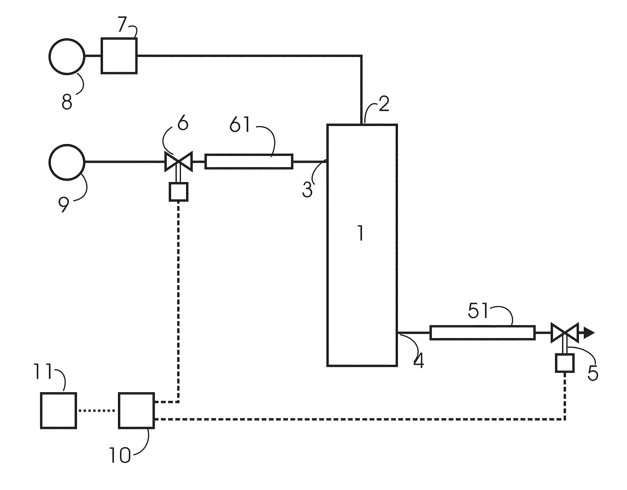
[0086]FIG. 3 illustrates for this first embodiment and in a schematic manner without implying scale, the time-response of gas pressure within the fibres, P2, and liquid pressure outside the fibres, P4, through a sequence which includes a period during which liquid flows during dispense and also a period when liquid is not flowing. FIG. 3 also illustrates the corresponding time-response through the same sequence of gas flow rate through port 2, F2, and liquid flow rate through port 4, F4.
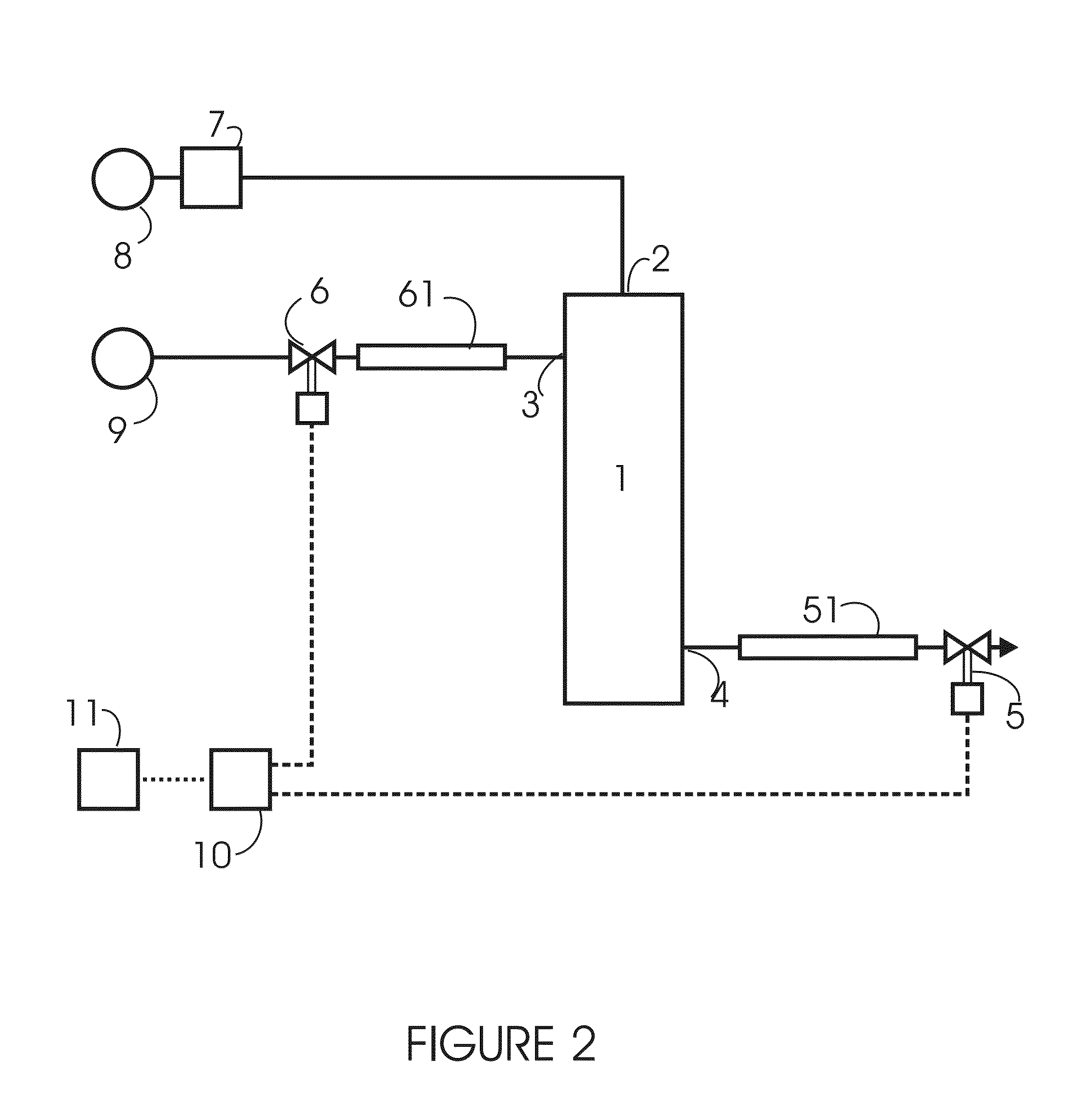
[0087]Dispense liquid flow F4 into the contactor is started at time T0 when both valves 5 and 6 are opened simultaneously, and is stopped at time T1 when valve 6 closes.
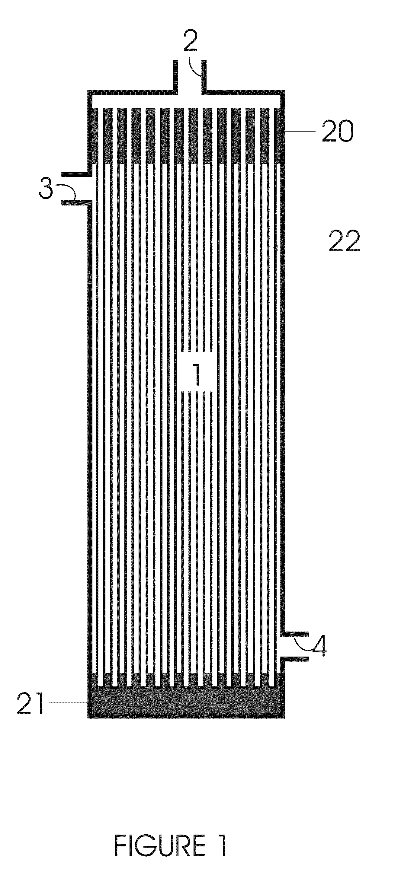
[0088]The gas pressure applied to the fibres 1 is maintained at P2 at all times. This pressure determines the maximum amount of gas which can be dissolved in the liquid. As will be explained below, the pressures P2 and P4 are equal prior to the start of each dispense. At such time the liquid contained within 1 will therefore usually b...
second embodiment
[0112]The resulting changes of pressures in response to dispense flow and to operation of valves 5 and 6 through switch 52 and control unit 93 are the same as previously described for the second version of the second embodiment, and illustrated in FIG. 5.
third embodiment
[0113]It will be appreciated that the arrangement illustrated in FIG. 4 requires a manual dispense tap 53 modified to accept flow via valve 5 to its outlet, and that this arrangement results in a small volume being over-dispensed or being wasted. The third embodiment is thus to be preferred in circumstances where the dispense tap 53 is not modified, and in circumstances where it would be undesirable to allow wastage of the small amount of liquid released by valve 5 after closure of valve 6.
[0114]Turning now to the embodiments of FIGS. 7 to 10, for clarity and because the details are not relevant to the present disclosure, details of features and components relating to temperature control of the liquid have been omitted from the circuit diagrams.
[0115]Gas port 2 of contactor 1 is connected to a gas source 101 via a pressure regulator 102 which is of the type generally known as a relieving regulator, which signifies that it will if necessary vent excess gas from its output side to mai...
PUM
| Property | Measurement | Unit |
|---|---|---|
| pressure | aaaaa | aaaaa |
| temperature | aaaaa | aaaaa |
| flow rate | aaaaa | aaaaa |
Abstract
Description
Claims
Application Information
 - R&D
- Intellectual Property
- Life Sciences
- Materials
- Tech Scout
- Unparalleled Data Quality
- Higher Quality Content
- 60% Fewer Hallucinations
Browse by: Latest US Patents, China's latest patents, Technical Efficacy Thesaurus, Application Domain, Technology Topic, Popular Technical Reports.
© 2025 PatSnap. All rights reserved.Legal|Privacy policy|Modern Slavery Act Transparency Statement|Sitemap|About US| Contact US: help@patsnap.com


