Acoustic determination of piston position in a modular dynamics tester displacement pump and methods to provide estimates of fluid flow rate

a modular dynamics and displacement pump technology, applied in the direction of positive displacement liquid engine, pump parameter, instruments, etc., can solve the problem of affecting the operation of the pump speed, and achieve the effect of improving the pump speed

Active Publication Date: 2016-05-17
SCHLUMBERGER TECH CORP
View PDF10 Cites 0 Cited by
  • Summary
  • Abstract
  • Description
  • Claims
  • Application Information

AI Technical Summary

Problems solved by technology

Conventional systems and methods do not accurately determine the position of a piston surface and therefore the inherent problems of pressure surges and improper pump speeds pervade the operations of these systems.

Method used


Image

  • Acoustic determination of piston position in a modular dynamics tester displacement pump and methods to provide estimates of fluid flow rate
  • Acoustic determination of piston position in a modular dynamics tester displacement pump and methods to provide estimates of fluid flow rate
  • Acoustic determination of piston position in a modular dynamics tester displacement pump and methods to provide estimates of fluid flow rate

Examples


Embodiment Construction

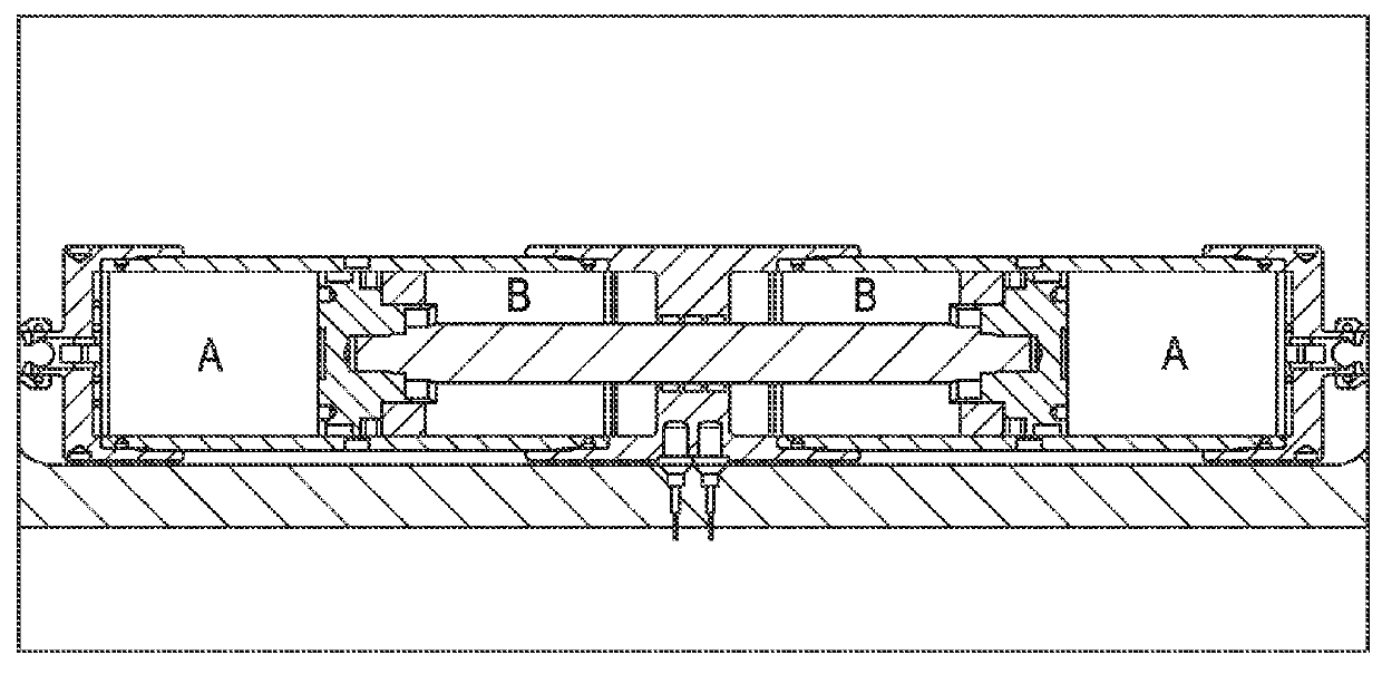
[0016]There are numerous methods that may be used to determine the position of the piston within the cylinder and these include, but are not limited to, the following: (1) a Linear Variable Displacement Transducer (LVDT) as provided by a rod moving within a toroidal magnet, (2) a magnet positioned outside the cylinder moving in response to the piston position and detected with a method analogous to item 1, and (3), acoustic methods.

[0017]Aspects described utilize acoustic methods provided above in item three (3). Particularly, measurement of the time-of-flight of a pulse of sound as provided in FIGS. 2 and 3 is used. An acoustic transducer T is located either flush with the cylinder end or incorporated into a screen S as provided in FIGS. 2 and 3. The sound emitted as a pulse by an acoustic transducer T is reflected by the acoustic impedance mismatch at the surface R, which is parallel with the transducer T, and travels a distance 2l before arrival at the transducer T that is now ac...


PUM


Abstract

A method for determining a piston position in a downhole tool, having steps of providing a transducer in the downhole tool, wherein the tool has a piston used to create a vacuum for the downhole tool, providing a transducer tone burst to provide acoustic energy toward the piston, reflecting the transducer tone burst by a surface of the piston, receiving the transducer tone burst at a receiver, calculating time of flight for the transducer tone burst and determining the piston position in the downhole tool based upon the calculated time of flight of the transducer tone burst.

Description

CROSS-REFERENCE TO RELATED APPLICATIONS[0001]None.FIELD OF THE INVENTION[0002]Aspects relate to the use of acoustic apparatus in downhole operations. More specifically, aspects relate to acoustic determination of piston position in a modular dynamics tester displacement pump.BACKGROUND INFORMATION[0003]Modular dynamics testers are used to acquire amounts of reservoir fluid for analysis and transportation. The reservoir fluid is drawn into the modular dynamics tester through a probe that is placed in contact with the bore-hole wall. The placement is accomplished by reducing the pressure within the modular dynamics tester tubular that initially contains bore-hole fluid, from the pressure of the formation.[0004]Pressure reduction used for placing the modular dynamics tester tubular is generated by a positive displacement pump operated by hydraulic fluid. In conventional apparatus and methods, piston position is determined with a transducer that is based on the Hall effect. Such convent...

Claims


Application Information

Patent Timeline
Patent Type & Authority Patents(United States)
IPC IPC(8): F15B15/28F04B51/00F04B47/04G01S15/88G01S7/52G01S15/10F04B1/00
CPCG01S15/10G01S15/88F04B1/00F04B47/04F04B51/00G01S7/52006F04B2201/0201F15B15/2884
Inventor GOODWIN, ANTHONY R. H.APOTEKER, AUDREYBEDOUET, SYLVAINJACQUEME, FREDERIC
Owner SCHLUMBERGER TECH CORP
Why Eureka
Try Eureka