
Configurations and methods of Co2 capture from flue gas by cryogenic desublimation

a technology of co2 and flue gas, which is applied in the field of systems and methods of co2 desublimation from flue gas, can solve the problems of solvent environmental concerns, significant expenses, and the degradation of most solvents (and especially amine solvents) through oxidation

Active Publication Date: 2016-05-17
FLUOR TECH CORP
View PDF15 Cites 16 Cited by
  • Summary
  • Abstract
  • Description
  • Claims
  • Application Information

AI Technical Summary

Benefits of technology

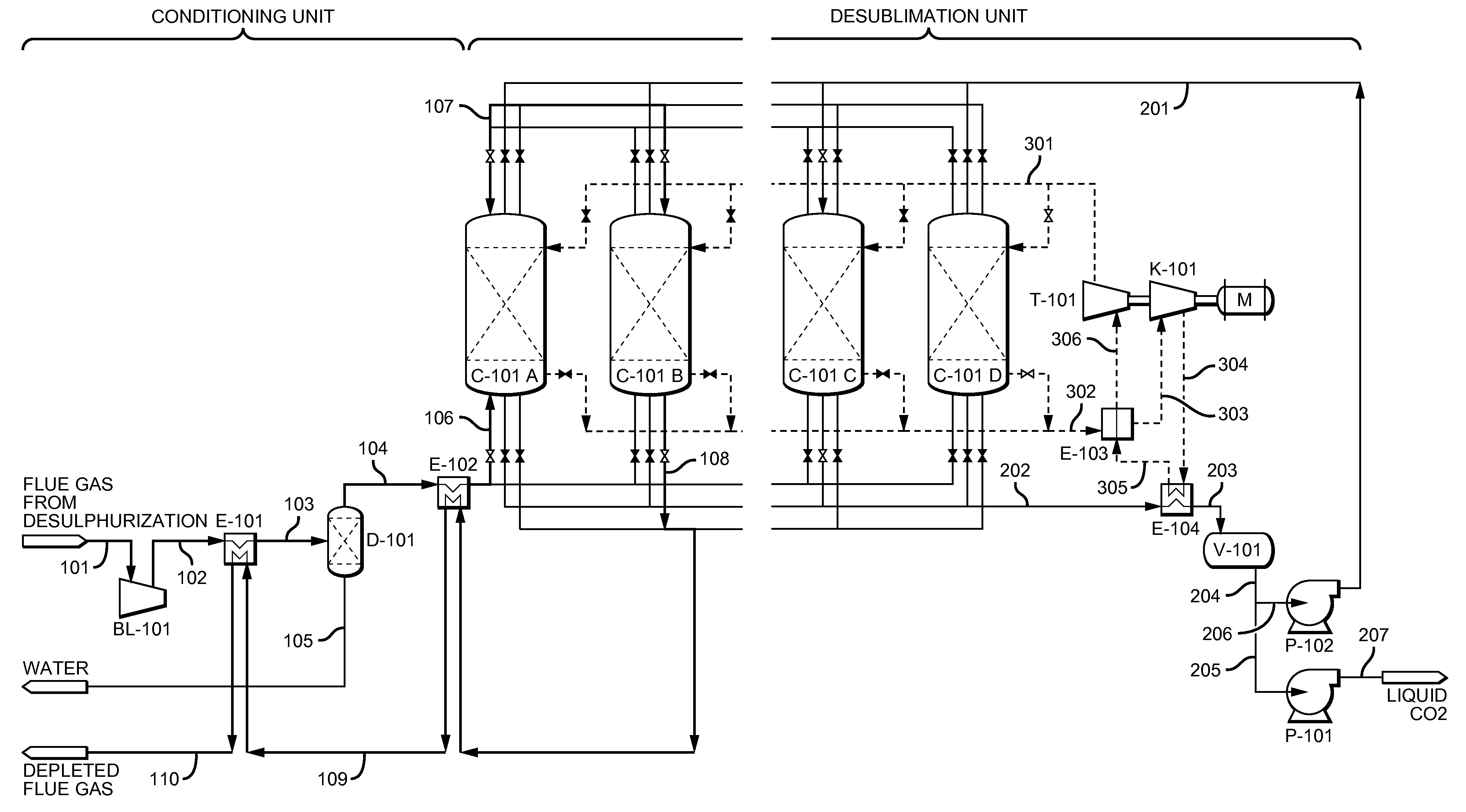
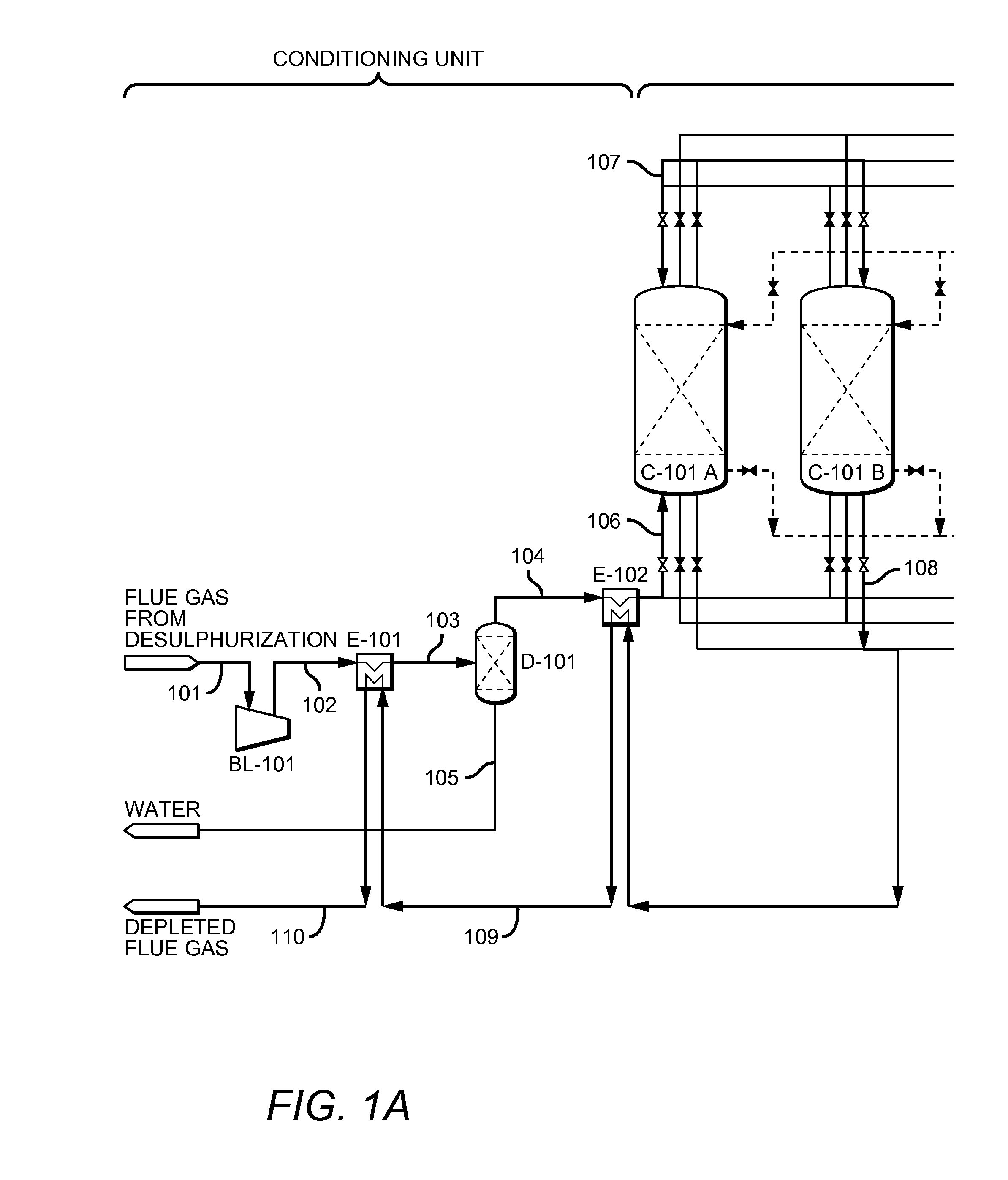
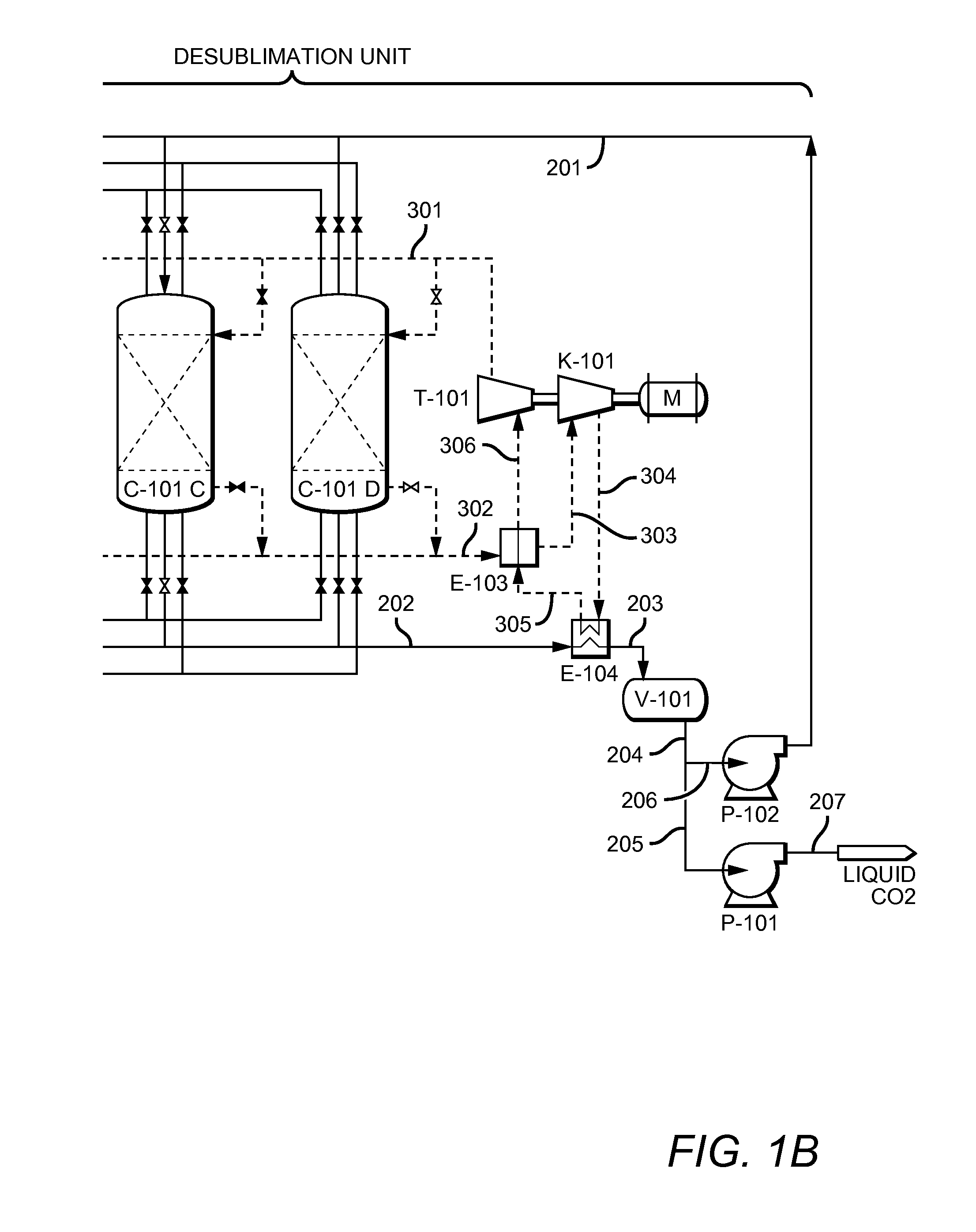
The present invention is about a method and system for removing CO2 from flue gas using a plurality of desublimators that recycle refrigeration content. The system includes a flue gas conditioning unit that cools the flue gas using a cool CO2-lean flue gas and a refrigeration cycle that uses residual refrigeration content to cool the refrigerant. The system also includes a control system and valves that allow for switching between different modes of operation for the desublimators. The technical effects of this invention include efficient removal of CO2 from flue gas with recycling of refrigeration content, improved energy efficiency, and reduced emissions of CO2.

Problems solved by technology

This method is effective, however presents several difficulties: (1) solvents must be manufactured, purchased, and transported, resulting in significant expenses; (2) most solvents (and especially amine solvents) tend to degrade via oxidative and / or thermal pathways.
As a consequence the solvent must be maintained and / or continuously replaced; and (3) some solvents present environmental concerns as they may form harmful compounds once emitted to the atmosphere.
However, these processes are often costly because they carry energy penalties caused by the regeneration of CO2 loaded adsorbents or by the need for recompression of flue gas upstream of a membrane.
While such process is at least conceptually attractive, significant energy requirements often render such separation impracticable.
Such configuration, however, is typically not able to generate a pure CO2 stream and requires in most cases substantial quantities of energy for CO2 recovery.
However, use of such porous media may be problematic due to potential clogging.
Furthermore, CO2 recovery using liquid CO2 as described in the '537 reference is not energy efficient under various circumstances.

Method used


Image

  • Configurations and methods of Co<sub>2 </sub>capture from flue gas by cryogenic desublimation
  • Configurations and methods of Co<sub>2 </sub>capture from flue gas by cryogenic desublimation
  • Configurations and methods of Co<sub>2 </sub>capture from flue gas by cryogenic desublimation

Examples


Embodiment Construction

[0019]The inventive subject matter is directed to various systems and methods for CO2 removal from flue gas using desublimation that are particularly effective in the recovery of refrigeration content from streams within the system.

[0020]In general, contemplated systems and methods allow for CO2 separation from flue gas as a result of differences in intrinsic thermodynamic properties between CO2 and other components in the flue gas. More specifically, the inventors have developed systems and methods to capture solid CO2 through desublimation at relatively low pressure, and recovery of the solid CO2 via use of liquid CO2 at relatively high pressure.

[0021]As the process of CO2 desublimation is energy demanding, the inventors have developed systems and methods to recycle refrigeration content that allows substantially more economical operation. In one particularly preferred aspect, thermal integration between the flue gas entering the desublimators and the CO2-lean effluent gas, and th...


PUM

PropertyMeasurementUnit
temperatureaaaaaaaaaa

Abstract

Systems and methods of CO2 desublimation are presented in which refrigeration content is retained within the system. Most preferably, refrigeration content is recycled by providing the refrigeration content of a CO2-lean feed gas to the CO2-containing feed gas and to pre-cooling of a desublimator, and / or by providing refrigeration of effluent of a desublimator in regeneration to a refrigerant in a closed refrigeration cycle for deep-cooling of another desublimator.

Description

[0001]This application claims priority to U.S. provisional application with the Ser. No. 61 / 670,427, which was filed on Jul. 11, 2012, and which is incorporated by reference herein.FIELD OF THE INVENTION[0002]The field of the invention is systems and methods of CO2 desublimation from flue gas and recovery thereof.BACKGROUND OF THE INVENTION[0003]The increasing carbon dioxide concentration in the atmosphere is suggested to be linked to increasing temperatures and changes in the World's climate, and significant interest has been given to CO2 capture, especially from combustion gases. One well established CO2 capture method uses a chemical solvent (typically amine based) to absorb CO2 from flue gas. This method is effective, however presents several difficulties: (1) solvents must be manufactured, purchased, and transported, resulting in significant expenses; (2) most solvents (and especially amine solvents) tend to degrade via oxidative and / or thermal pathways. As a consequence the so...

Claims


Application Information

Patent Timeline
Patent Type & Authority Patents(United States)
IPC IPC(8): F25J3/00F25J1/00B01D53/00B01D7/02F25J3/06B01D7/00
CPCB01D53/002B01D7/00B01D7/02F25J3/067B01D2257/504B01D2258/0283F25J2205/20F25J2210/70Y02C10/12Y02P70/34Y02P70/10Y02C20/40B01D53/265
Inventor REDDY, SATISHYONKOSKI, JOSEPHMATHIAS, PAUL
Owner FLUOR TECH CORP
Learn More