
Receiver module for solar power station with in-built thermal monitoring

a solar power station and receiver module technology, applied in the direction of solar heat collectors for particular environments, solar radiation concentration, solar heat collector safety, etc., can solve the problems of permanent deformation and damage to the structure, complex and bulky devices, and inability to properly align and/or focus solar flux reflected by mirrors relative to the absorber

Active Publication Date: 2016-04-26
COMMISSARIAT A LENERGIE ATOMIQUE ET AUX ENERGIES ALTERNATIVES
View PDF21 Cites 2 Cited by
  • Summary
  • Abstract
  • Description
  • Claims
  • Application Information

AI Technical Summary

Benefits of technology

[0022]One aim of the present invention is consequently to provide a solar receiver of simple and robust construction, in which an alignment fault and / or a fault of focusing of the solar flux on the absorber may easily be detected.
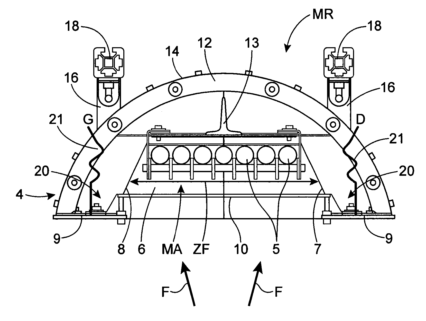
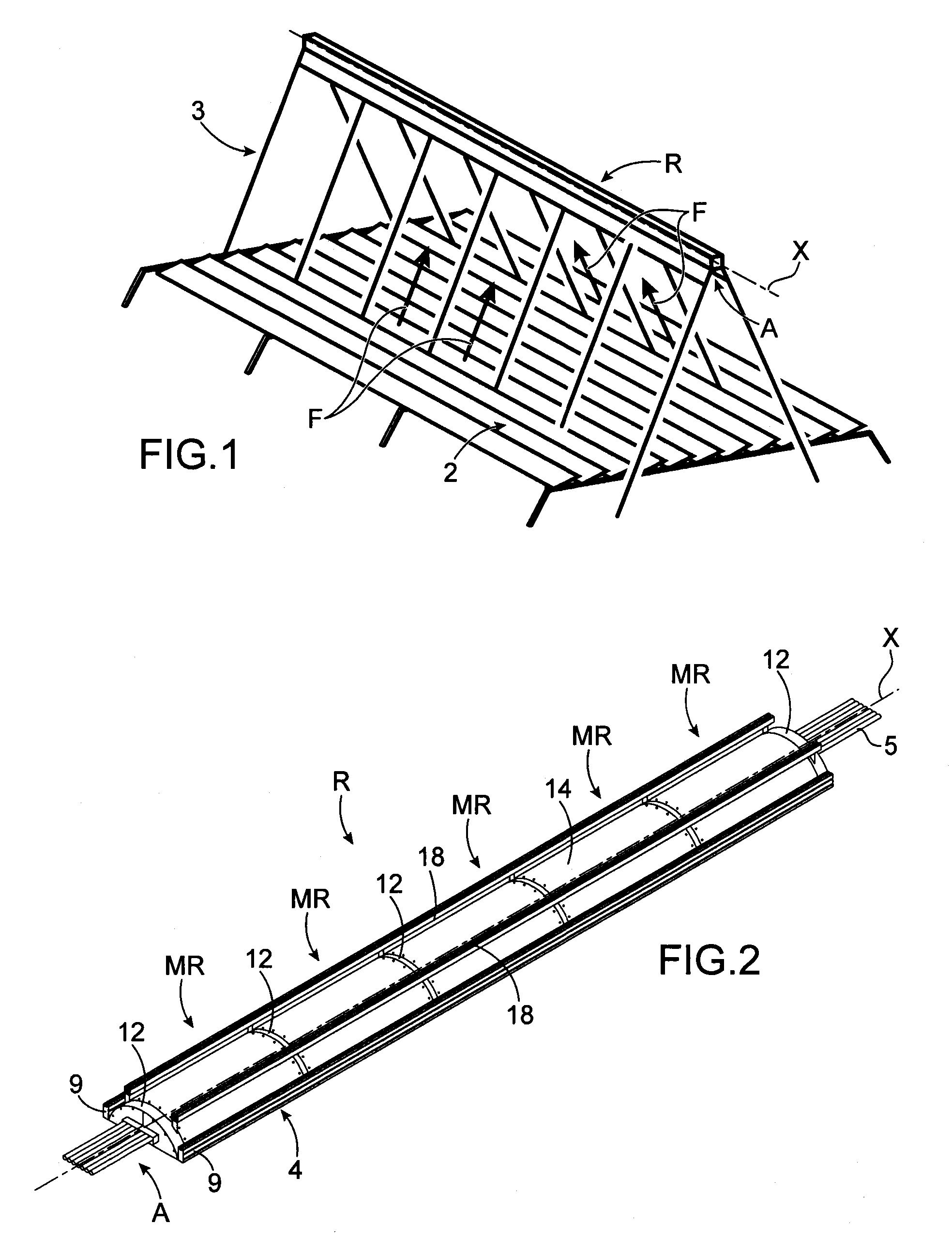
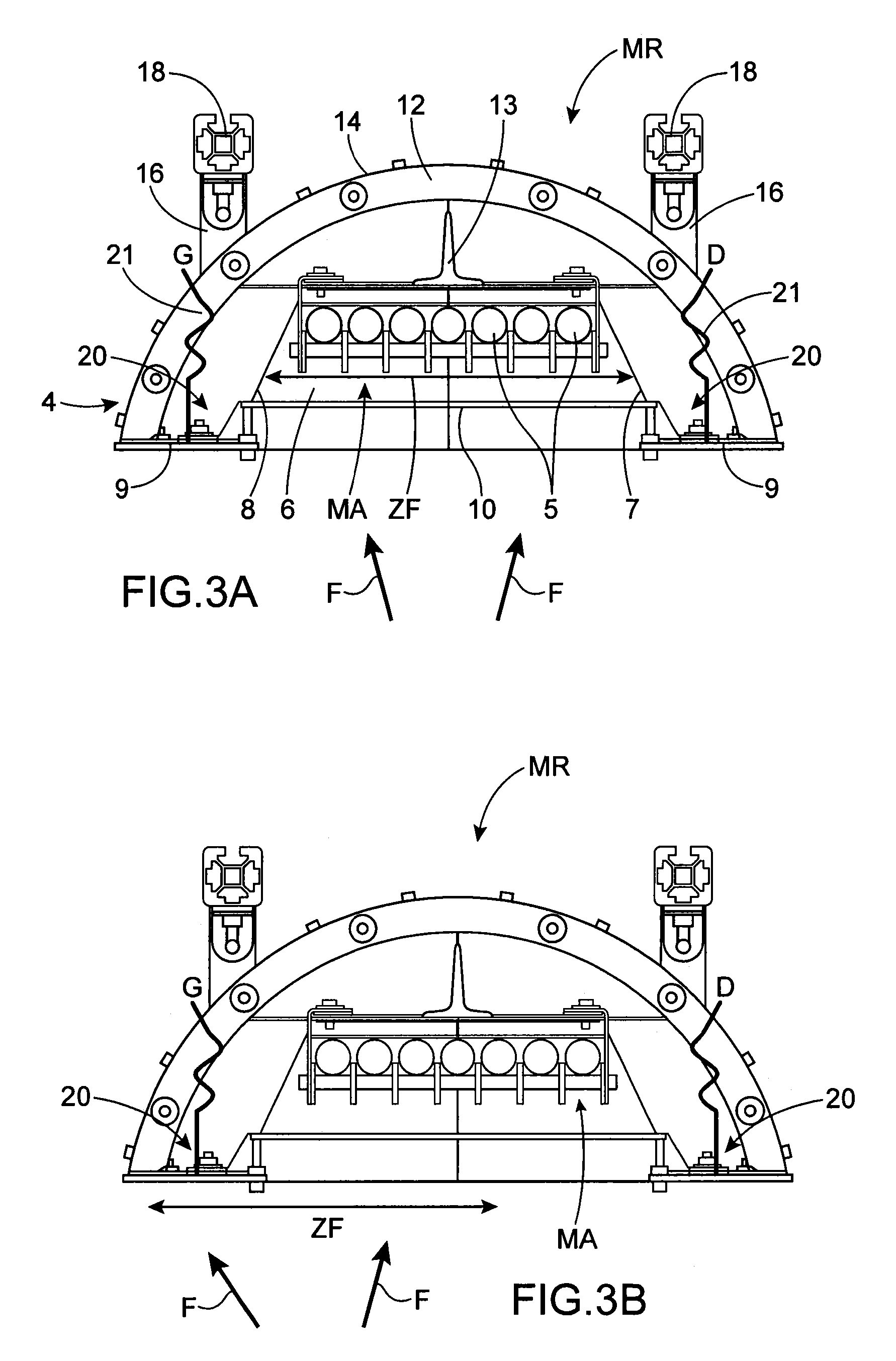
[0025]By virtue of the invention, the detection of the appearance of a temperature difference at the edges of the structure around the cavity enables qualitative information to be obtained concerning the type of fault which the flux has: either it is aligned too much to the left relative to the absorber, or it is aligned too much to the right relative to the absorber and / or it is diffuse. The thermal changes of the structure and the general operation of the power station may therefore be monitored without having quantitative data concerning the flux, but solely by having available qualitative data concerning its state of alignment / focusing and / or of diffusion. This detection is also obtained in a very simple and very reliable manner.
[0026]Advantageously, knowledge of the value of the temperature difference may enable even more thorough monitoring of the power station to be undertaken.

Problems solved by technology

It is possible that the solar flux reflected by the mirrors may not be correctly aligned and / or focused relative to the absorber, and the concentrated solar patch may then illuminate a portion of the metal structure, instead of illuminating only the absorber.
In addition to the fact that a portion of the reflected flux is not transmitted to the heat transfer fluid and is consequently lost, the metal structure is heated.
The structure is then subject to thermal cycles which may cause permanent deformations and damage to the structure.
This device is complex and bulky, requires substantial maintenance, and gives no information on the metal structure.
In addition, this device does not enable a problem of focusing and / or mirrors to be detected dynamically during operation.

Method used


Image

  • Receiver module for solar power station with in-built thermal monitoring
  • Receiver module for solar power station with in-built thermal monitoring
  • Receiver module for solar power station with in-built thermal monitoring

Examples


Embodiment Construction

[0022]One aim of the present invention is consequently to provide a solar receiver of simple and robust construction, in which an alignment fault and / or a fault of focusing of the solar flux on the absorber may easily be detected.

[0023]The stated aim is attained by a solar receiver having a metal structure, at least one absorber supported by the metal structure and means positioned in the metal structure to detect a temperature difference compared to a reference temperature for this structure. This temperature difference is representative of a positioning fault and / or fault of focusing of the solar flux on the absorber.

[0024]In other words, a positioning and / or focusing fault of the concentrated solar patch by the appearance of a temperature difference of the metal structure, in proximity to the absorber, compared to its temperature in an optimum operating condition, in which the solar patch illuminates only the absorber, is detected.

[0025]By virtue of the invention, the detection o...


PUM


Abstract

A receiver module for a solar power station receiver, including a metal structure and an absorber module, the metal structure defining a cavity extending along a longitudinal axis in a base of which the absorber module is housed. The cavity includes an aperture configured to be aligned towards at least one mirror of the solar power station, the aperture is edged by two side portions of the metal structure extending longitudinally on either side of the cavity. The receiver module also includes thermocouples positioned on each of the side portions relative to the longitudinal axis to detect a temperature difference between a reference temperature and two points of the metal structure that are opposite relative to the longitudinal axis.

Description

TECHNICAL FIELD AND PRIOR ART[0001]The present invention relates to a solar receiver module for a solar power station with integrated thermal monitoring, to a solar receiver comprising at least two such receiver modules, and to a concentrating solar power station of the Fresnel type comprising at least one such receiver.[0002]Concentrating thermal solar technology consists in using solar radiation to heat a heat transfer fluid used as the heat source in a thermodynamic cycle. Concentration enables relatively high temperatures to be attained, and thus relatively substantial thermodynamic conversion efficiencies to be enjoyed. The developed technologies are distinguished by the means used to concentrate the solar rays, by the means by which heat is transferred, and possibly by the means used to store heat, i.e. the heat transfer fluid used and thermodynamic conversion means which are, for example, steam turbines, gas turbines or Stirling engines.[0003]There are typically four families...

Claims


Application Information

Patent Timeline
Patent Type & Authority Patents(United States)
IPC IPC(8): F24J2/46F24J2/38F24J2/40F24J2/16F24J2/07F24J2/10F24S20/20F24S23/70F24S23/77F24S50/20
CPCF24J2/07F24J2/16F24J2/38F24J2/402F24J2/4621F24J2002/385Y02E10/41Y02E10/47F24J2002/108F24S20/20F24S23/77F24S40/50F24S50/20F24S50/40F24S2023/872F24S2050/25Y02E10/40
Inventor COUTURIER, RAPHAELBRUCH, ARNAUD
Owner COMMISSARIAT A LENERGIE ATOMIQUE ET AUX ENERGIES ALTERNATIVES
Learn More