
Image processing apparatus, control method, and program for the same with focus state specification and deletion confirmation of image data

a control method and image data technology, applied in the field of image processing techniques, can solve the problems of deleting image data accidentally without confirming a desired focused image, and the technique does not determine whether or not a focused image is displayed

Active Publication Date: 2016-04-19
CANON KK
View PDF10 Cites 0 Cited by
  • Summary
  • Abstract
  • Description
  • Claims
  • Application Information

AI Technical Summary

Benefits of technology

[0008]The present invention provides an image processing apparatus that can confirm a desired focused image by a user upon deletion operation of image data in which the focus state is specifiable.
[0010]According to the present invention, an image processing apparatus that can confirm a desired focused image by a user upon deletion operation of image data in which the focus state is specifiable may be provided.

Problems solved by technology

However, when a user performs a deletion operation for an image captured by a light-field camera, image data may accidentally be deleted without confirming a desired focused image if the image data is processed by the specification of focus information by the user.
Although the technique disclosed in Japanese Patent Laid-Open No. 2008-289065 prohibits the deletion of multi-viewpoint image data without permission, the technique does not determine whether or not a focused image being displayed is an image which is desired to be confirmed by a user upon deletion.

Method used


Image

  • Image processing apparatus, control method, and program for the same with focus state specification and deletion confirmation of image data
  • Image processing apparatus, control method, and program for the same with focus state specification and deletion confirmation of image data
  • Image processing apparatus, control method, and program for the same with focus state specification and deletion confirmation of image data

Examples


first embodiment

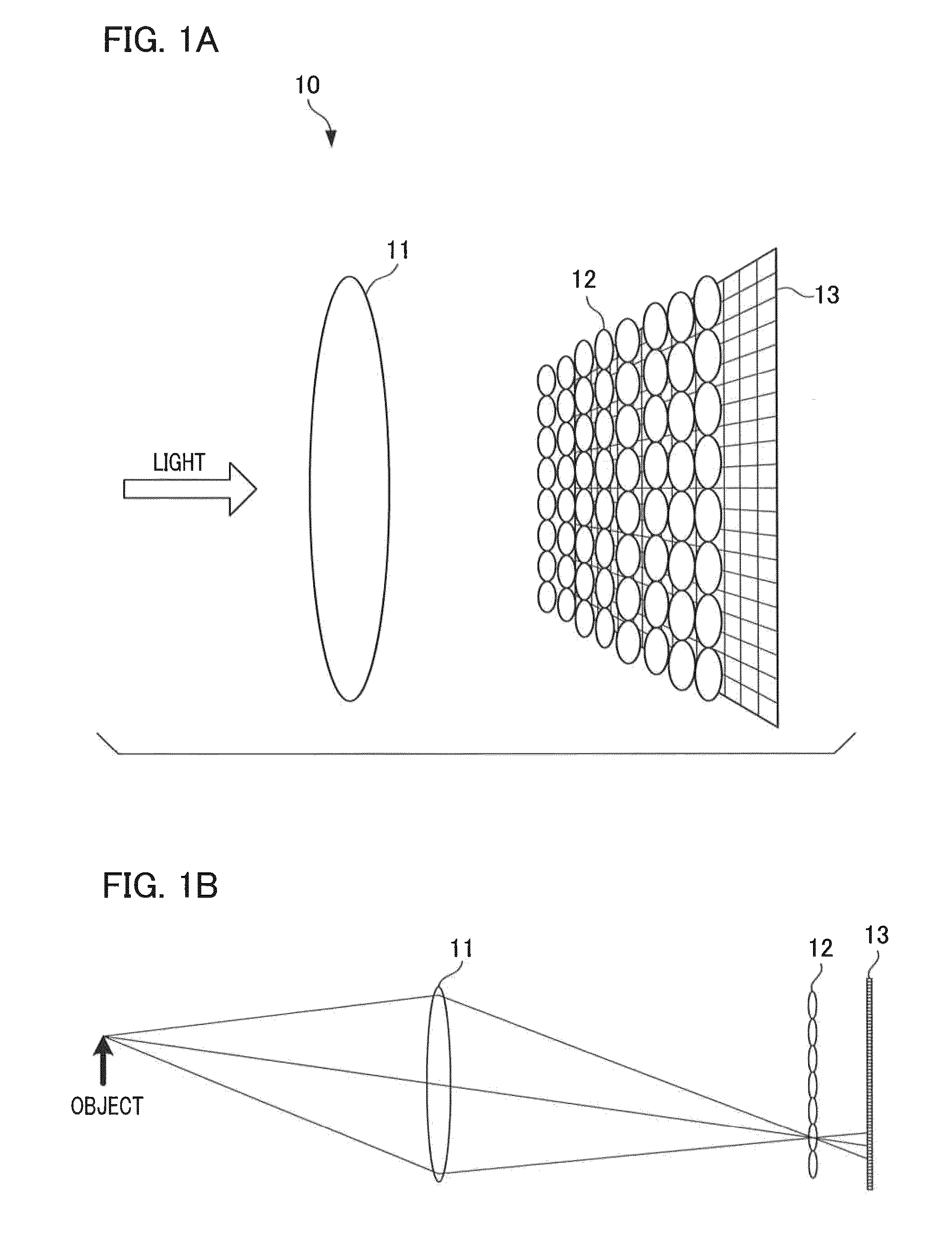
[0033]FIGS. 1A and 1B are schematic diagrams illustrating an example of the internal configuration of a light-field camera. Light from an object, which is incident on a micro lens array 12 by passing through an imaging lens 11, is photoelectrically converted into an electrical signal by an image sensor 13. Note that the obtained imaging data is referred to as “light-field data” (hereinafter referred to as “LF data”).

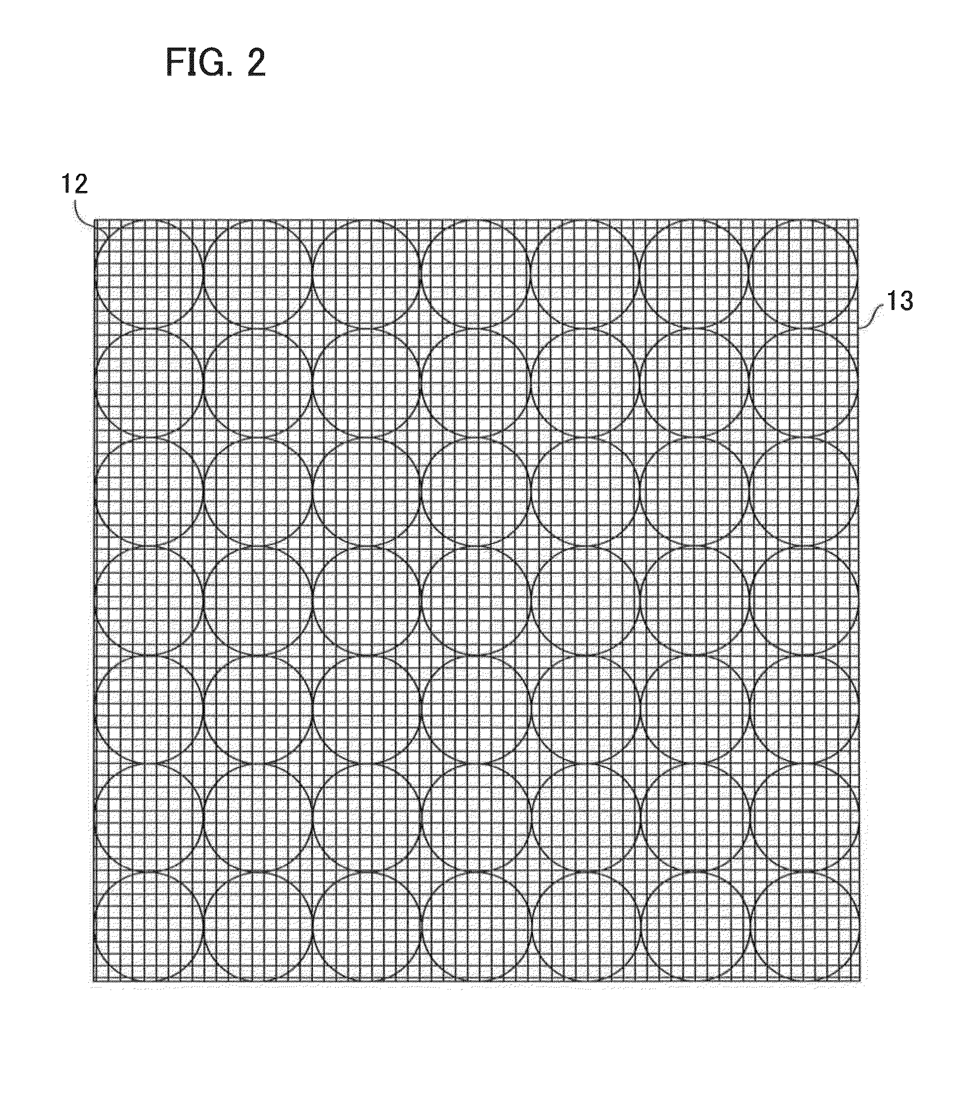
[0034]The imaging lens 11 projects light from an object onto the micro lens array 12. The imaging lens 11 is an interchangeable lens that is mounted to the main body of an imaging apparatus 10. A user can change an imaging magnification by the zoom operation of the imaging lens 11. The micro lens array 12 is configured by arranging a plurality of micro lenses in a grid and is located between the imaging lens 11 and the image sensor 13. Each of the micro lenses constituting the micro lens array 12 divides incident light from the imaging lens 11 into divided light componen...

second embodiment

[0070]Next, a description will be given of a second embodiment of the present invention. In the second embodiment, a description will be given of an example in which an image prior to specification of focus information and a deep focus image are simultaneously displayed when a deletion operation for deleting an image file in which focus information can be arbitrarily specified is performed. A deep focus image is an image in which all objects which are capable of being focused are in focus. According to the light field technique, a deep focus image can be generated.

[0071]Hereinafter, a description will be given mainly of the differences from the first embodiment. Components corresponding to or similar to those in the first embodiment are designated by the same reference numerals, and therefore, its explanation will be omitted. A description of the embodiments to be described below will be omitted in the same way.

[0072]FIG. 14 is a flowchart illustrating an example of processing perfo...

third embodiment

[0081]Next, a description will be given of a third embodiment of the present invention. In the third embodiment, a description will be given of a configuration in which an imaging apparatus is integrated with a display device.

[0082]FIG. 18 is a block diagram illustrating an example of a configuration of an imaging apparatus 200. The differences from FIG. 1 are the imaging lens 11, the micro lens array 12, and the image sensor 13.

[0083]When an operation signal is input by a user operation and the signal is a shutter operation signal for providing an instruction to record light beam information and directional information, the operation input unit 101 outputs an instruction for recording light beam information and directional information to the image sensor 13. When the image sensor 13 receives an instruction for recording light beam information and directional information, the image sensor 13 performs storage processing by outputting LF data including the detected light beam informat...


PUM


Abstract

An image processing apparatus generates an image data in which a focus state of a captured image is specified by calculation processing. An operation inputting unit is used for operating focus information for specifying the focus state of an image, and an image generating unit generates an image data by acquiring focus information. When image focus information is changed by specification made by a user, the image generating unit outputs the image data generated by using focus information prior to specification to a confirmation screen generating unit upon deletion operation of the image data. The confirmation screen generation unit generates a display data of a deletion confirmation screen for prompting a user to confirm deletion upon deletion operation of an image file. The display data of a deletion confirmation screen includes the image data generated by using focus information differing from the changed focus state.

Description

BACKGROUND OF THE INVENTION[0001]1. Field of the Invention[0002]The present invention relates to an image processing technique that reconstructs image data in which the focus state of a captured image is specifiable.[0003]2. Description of the Related Art[0004]In recent years, imaging apparatuses referred to as a “light-field camera” have been practically implemented. The imaging apparatus divides incident light into multiple light components by a micro lens array arranged on an image sensor so that the imaging apparatus can obtain light beam information by capturing light traveling in a plurality of directions. After shooting, the imaging apparatus executes predetermined calculation processing based on the intensity of light and the light incident direction so that an image with any focal distance and any depth of field (hereinafter collectively referred to as “focus information”) can be configured. The advantage of the light-field camera is that any image can be configured by exec...

Claims


Application Information

Patent Timeline
Patent Type & Authority Patents(United States)
IPC IPC(8): H04N5/232
CPCH04N5/23293H04N5/23212G02B27/0075G02B7/28H04N23/959H04N23/633
Inventor KAGAYA, SOSUKE
Owner CANON KK
Learn More