
Methods of making optical fiber with reduced hydrogen sensitivity

a technology of optical fiber and hydrogen sensitivity, which is applied in the field of making optical fibers, can solve the problems of reducing the sensitivity of hydrogen sensitivity of optical fiber, reducing the transmission loss of optical signals in the telecommunication window, and reducing so as to suppress the formation of non-bridging oxygen defects, reduce the concentration, and reduce the sensitivity of hydrogen sensitivity

Active Publication Date: 2016-04-12
CORNING INC
View PDF23 Cites 8 Cited by
  • Summary
  • Abstract
  • Description
  • Claims
  • Application Information

AI Technical Summary

Benefits of technology

The present patent describes a method for making optical fibers with low concentrations of non-bridging oxygen defects and low sensitivity to hydrogen. The method involves a controlled cooling protocol that suppresses the formation of non-bridging oxygen defects or facilitates their removal. The cooling is done at a specific rate that reduces the average temperature of the fiber from a high temperature to a lower temperature. By controlling the cooling rate, the method achieves high purity and quality of optical fibers.

Problems solved by technology

Due to the high draw temperatures, large draw down ratios and fast draw speeds, silica bonds can break and defects can be induced in the glass matrix in the optical fiber.
Some of these defects are oxidizing defects like the non-bridging oxygen (NBO) defects, which can react with hydrogen even at room temperature to form hydroxyl species.
Formation of hydroxyl species in optical fibers is undesirable because hydroxyl species absorb at wavelengths in the telecommunication window and lead to increased transmission losses of optical signals in the telecommunication window.

Method used


Image

  • Methods of making optical fiber with reduced hydrogen sensitivity
  • Methods of making optical fiber with reduced hydrogen sensitivity
  • Methods of making optical fiber with reduced hydrogen sensitivity

Examples


example 1

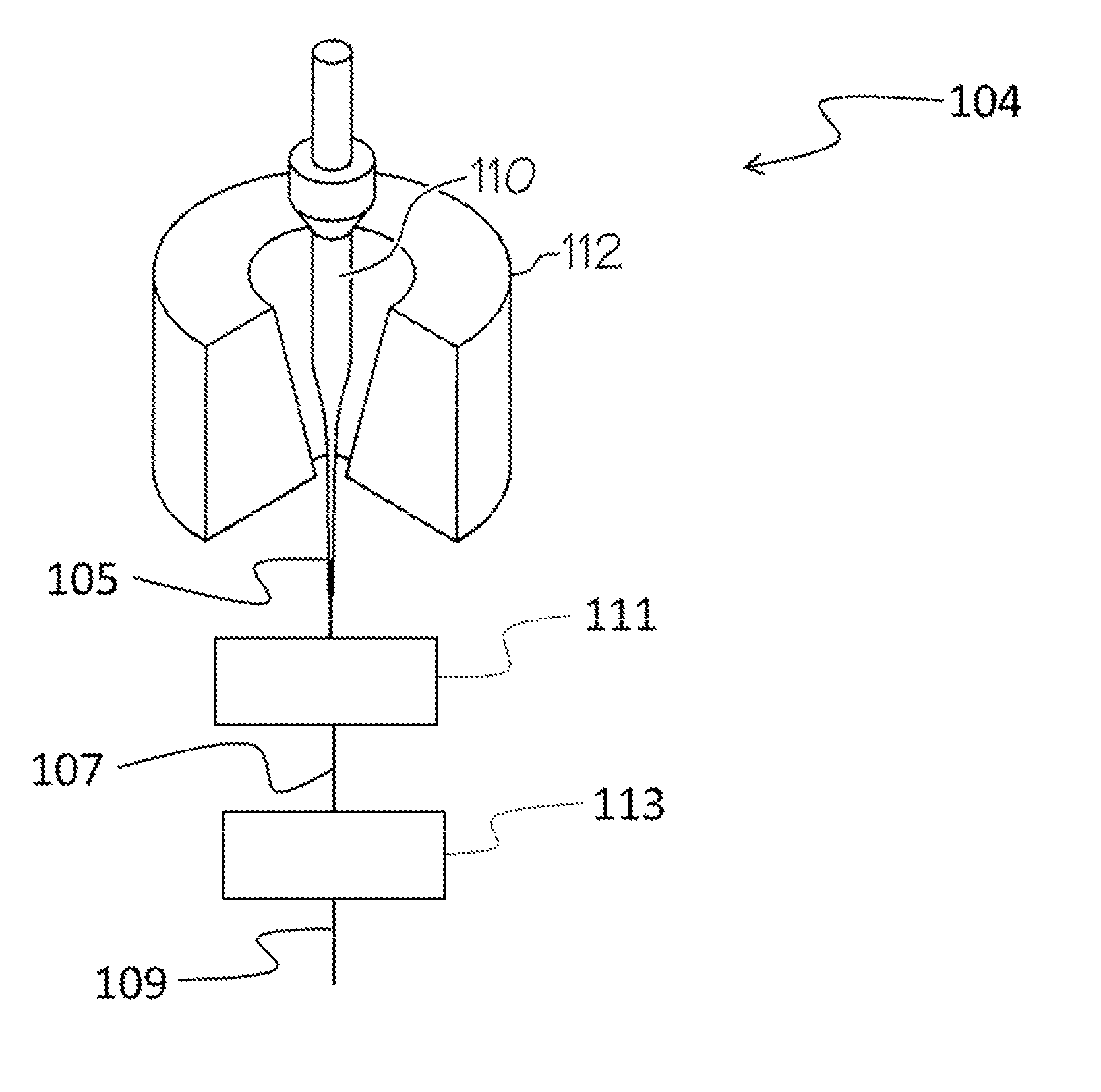
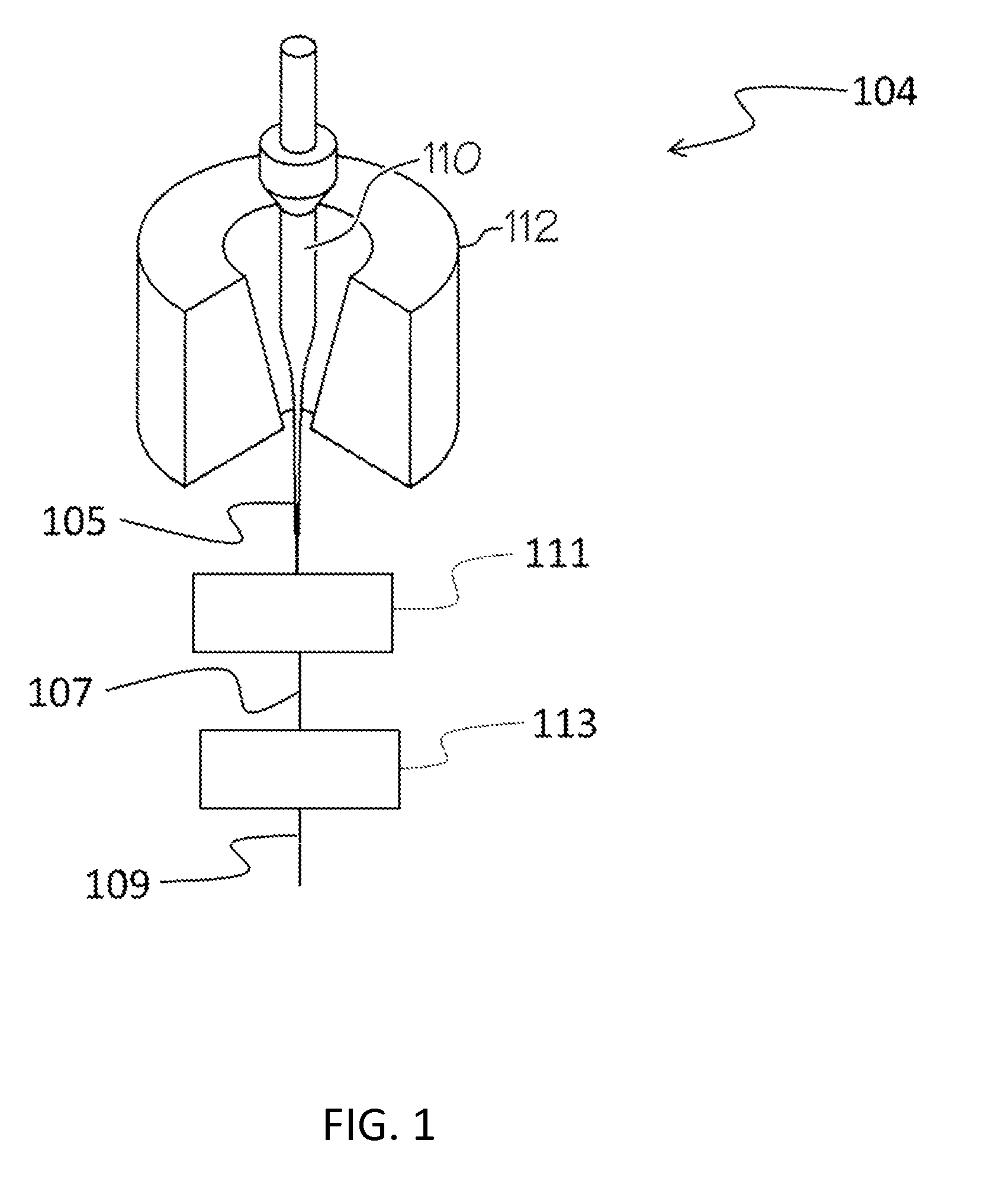
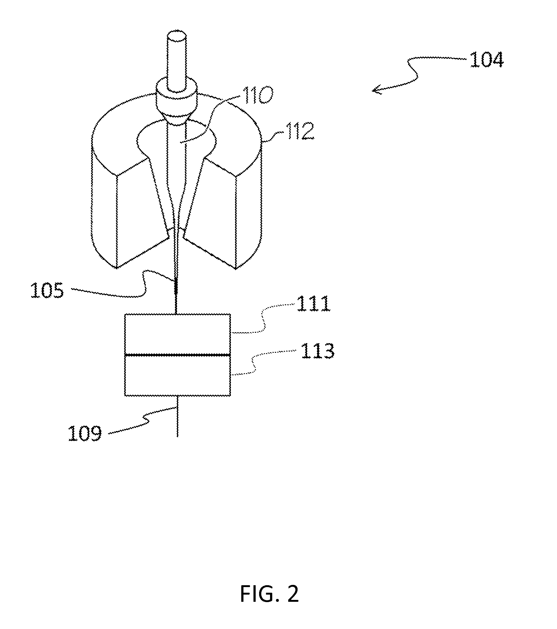
[0074]A series of six fibers was prepared under various treatment conditions to demonstrate the reduction in non-bridging oxygen defects provided by the methods of the present disclosure. Fibers were drawn from a single mode silica preform comprised of germania-doped core. The preform was heated to a draw temperature above 2000° C. in a drawing furnace in a vertical direction and transported to a series of two downstream treatment regions. The first treatment region included a heated zone maintained at 1200° C. The entrance average temperature of the fibers into the first treatment region was ˜1580° C. and the average temperature of the fibers exiting the first treatment region was in the range 1300° C.-1330° C. Fiber samples 1, 2, and 3 were cooled in the first treatment region at a rate of about 2500° C. / s and had a residence time in the first treatment region of about 0.20 sec. Fiber samples 4, 5, and 6 were cooled in the first treatment region at a rate of about 2850° C. / s and h...

example 2

[0078]In this example, fibers prepared using different cooling profiles are compared. The fibers were drawn in separate trials from the same apparatus and subjected to one of the two cooling profiles illustrated in FIG. 4. Each cooling profile in FIG. 4 shows the fiber surface temperature as a function of time, where a time of zero corresponds to the point in time at which the fiber has an average temperature of 1700° C. Cooling profile 1 represents a profile consistent with prior art fiber processing conditions, while cooling profile 2 represents a profile in accordance with the present disclosure.

[0079]For cooling profile 1, the fibers entered the first treatment region with an average fiber temperature of 1700° C., were cooled at an average rate of 7500° C. / s, and exited the first treatment region with an average fiber temperature of 1400° C. The fibers then entered a second treatment region with an average fiber temperature of 1400° C., were cooled at an average rate of 15,000° ...

example 3

[0082]In this example, the effect of the temperature of the heated region of the first treatment region on the non-bridging oxygen defect concentration of a series of seven fibers was considered. The fibers were prepared from a common optical fiber preform in a common drawing apparatus that included a drawing furnace, a first treatment region downstream from the drawing furnace, a second treatment region downstream from the first treatment region, and drawing mechanism. The second treatment region was directly adjacent the first treatment region and consisted of cooling the fiber in air. After exiting the first treatment region, each fiber was cooled in air in the second treatment region for the same residence time and then quenched. After quenching, the non-bridging oxygen defect concentration was measured.

[0083]The temperature of the heated zone of the first treatment region impacts the fiber temperature-time history in the first treatment region as well as the exit temperature of...


PUM

PropertyMeasurementUnit
temperatureaaaaaaaaaa

Abstract

A method of making optical fibers that includes controlled cooling to produce fibers having a low concentration of non-bridging oxygen defects and low sensitivity to hydrogen. The method may include heating a fiber preform above its softening point, drawing a fiber from the heated preform and passing the fiber through two treatment stages. The fiber may enter the first treatment stage at a temperature between 1500° C. and 1700° C., may exit the first treatment stage at a temperature between 1200° C. and 1400° C., and may experience a cooling rate less than 5000° C. / s in the first treatment stage. The fiber may enter the second treatment stage downstream from the first treatment stage at a temperature between 1200° C. and 1400° C., may exit the second treatment stage at a temperature between 1000° C. and 1150° C., and may experience a cooling rate between 5000° C. / s and 12,000° C. / s in the second treatment stage. The method may also include redirecting the fiber with a fluid bearing device or an air-turn device.

Description

[0001]This application claims the benefit of priority under 35 U.S.C. §119 of U.S. Provisional Application Ser. No. 61 / 863,560 filed on Aug. 8, 2013 the content of which is relied upon and incorporated herein by reference in its entirety.FIELD OF THE DISCLOSURE[0002]This disclosure pertains to methods of making optical fibers. More particularly, this disclosure relates to processing methods that provide optical fibers that exhibit reduced sensitivity to hydrogen. Most particularly, this disclosure relates to methods of making optical fibers that employ controlled cooling protocols to minimize the formation of non-bridging oxygen defects.BACKGROUND OF THE DISCLOSURE[0003]In the manufacturing of the optical fibers, the optical preforms are heated to temperatures much above the glass softening point and then drawn at large draw down ratios to form optical fibers 125 μm in diameter. Due to the high draw temperatures, large draw down ratios and fast draw speeds, silica bonds can break an...

Claims


Application Information

Patent Timeline
Patent Type & Authority Patents(United States)
IPC IPC(8): G02B6/00G02B6/10C03B37/10C03B37/07C03B37/027C03B37/03G02B6/02
CPCC03B37/02718C03B37/02727C03B37/032G02B6/02C03B37/07C03B37/10G02B6/10C03B2205/55C03B2205/56Y02P40/57
Inventor DUNWOODY, STEVEN AKINMOORE, ROBERT CLARKTANDON, PUSHKAR
Owner CORNING INC
Learn More