
Transporting apparatus and recording apparatus

a technology of transporting apparatus and recording apparatus, which is applied in the direction of printing, other printing apparatus, thin material processing, etc., can solve the problems of slowed sheet transport and damage to the printing surface,

Active Publication Date: 2016-04-12
SEIKO EPSON CORP
View PDF11 Cites 6 Cited by
  • Summary
  • Abstract
  • Description
  • Claims
  • Application Information

AI Technical Summary

Benefits of technology

[0007]An advantage of some aspects of the invention is to provide a transporting apparatus and a recording apparatus that can suppress generation of static electricity while an appropriate tension is applied to the medium that is being transported.
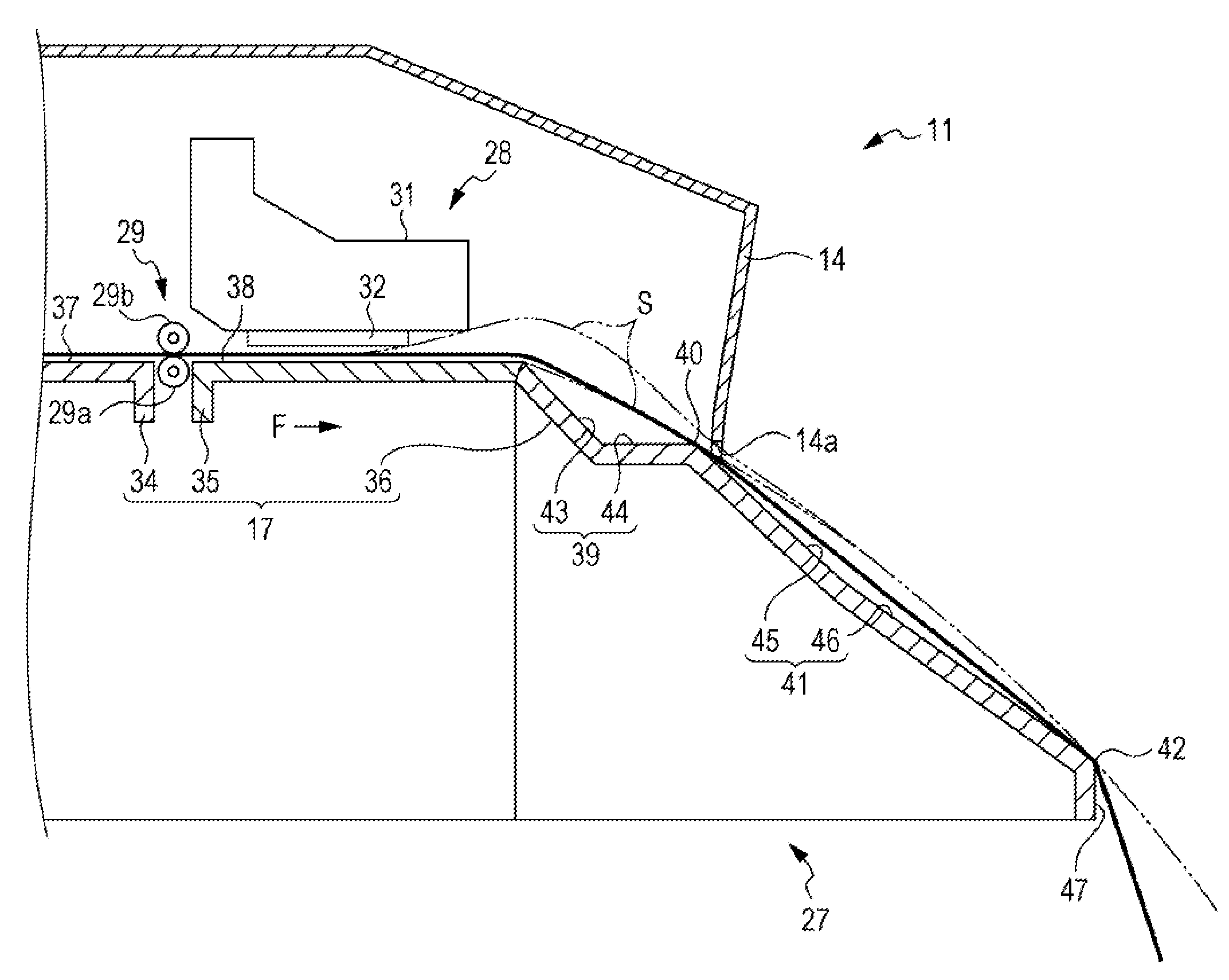
[0010]According to such a configuration, the guide portion is capable of guiding the leading edge of the medium, which is being transported by the transporting unit, in the transport direction from the medium supporting section side to the supporting projection side and, further, is capable of subsidiarily supporting the medium that has been deflected below the transport path. Since the guide portion forms a concavity with respect to the medium supporting section and the supporting projection, when the medium is supported by the medium supporting section and the supporting projection, contact between the guide portion and the medium is restrained. Moreover, the medium, whose upstream portion in the transport direction is supported by the medium supporting section, hangs down under its own weight at the upstream side or the downstream side of the supporting projection in the transport direction, and thus, an appropriate tension is applied to the medium. Accordingly, generation of static electricity can be suppressed while an appropriate tension is applied to the medium that is being transported.
[0014]According to such a configuration, when the leading edge of the medium is transported toward the supporting projection from the medium supporting section, the two or more guiding surfaces that are consecutively aligned in the transport direction guide the leading edge, and thus, the medium is not easily caught by the guide portion. Furthermore, the configuration can be simplified by forming the guide portion with the guide surfaces that are consecutively aligned in the transport direction.
[0020]According to such a configuration, the medium supporting section and the supporting projection can form a transport path that extends along the imaginary curve that becomes lower towards the downstream side in the transport direction. Accordingly, a portion of the medium, which is supported by the supporting projection, downstream in the transport direction hangs down under its own weight such that an appropriate tension is applied to the medium. Furthermore, the medium can be made to adequately part from the transport path by arranging the guide portion on the center of curvature side of the imaginary curve. Accordingly, when the medium is deflected so as to hang down between the medium supporting section and the supporting projection, the guide portion can subsidiarily support the medium while guiding the medium towards the downstream side in the transport direction.
[0024]According to such a configuration, similar effects to those of the transporting apparatus described above can be obtained.

Problems solved by technology

Accordingly, there are cases in which the sheet sticks to the support surface causing the transportation of the sheet to become slowed down.
Moreover, when transportation of the sheet, whose transportation has slowed down, is continued, the sheet becomes deflected, becomes lifted up from the support surface, and comes into contact with the members arranged along the transport path; accordingly, there is a concern that the printing surface may become damaged.
The above problem is not limited to printers that perform printing by ejecting ink onto roll paper but is a problem that is generally common among transporting apparatuses that transport a medium and recording apparatuses that are provided with such a transporting apparatus.

Method used


Image

  • Transporting apparatus and recording apparatus
  • Transporting apparatus and recording apparatus
  • Transporting apparatus and recording apparatus

Examples


Embodiment Construction

[0029]An exemplary embodiment of a transporting apparatus and a recording apparatus will be described below with reference to the drawings.

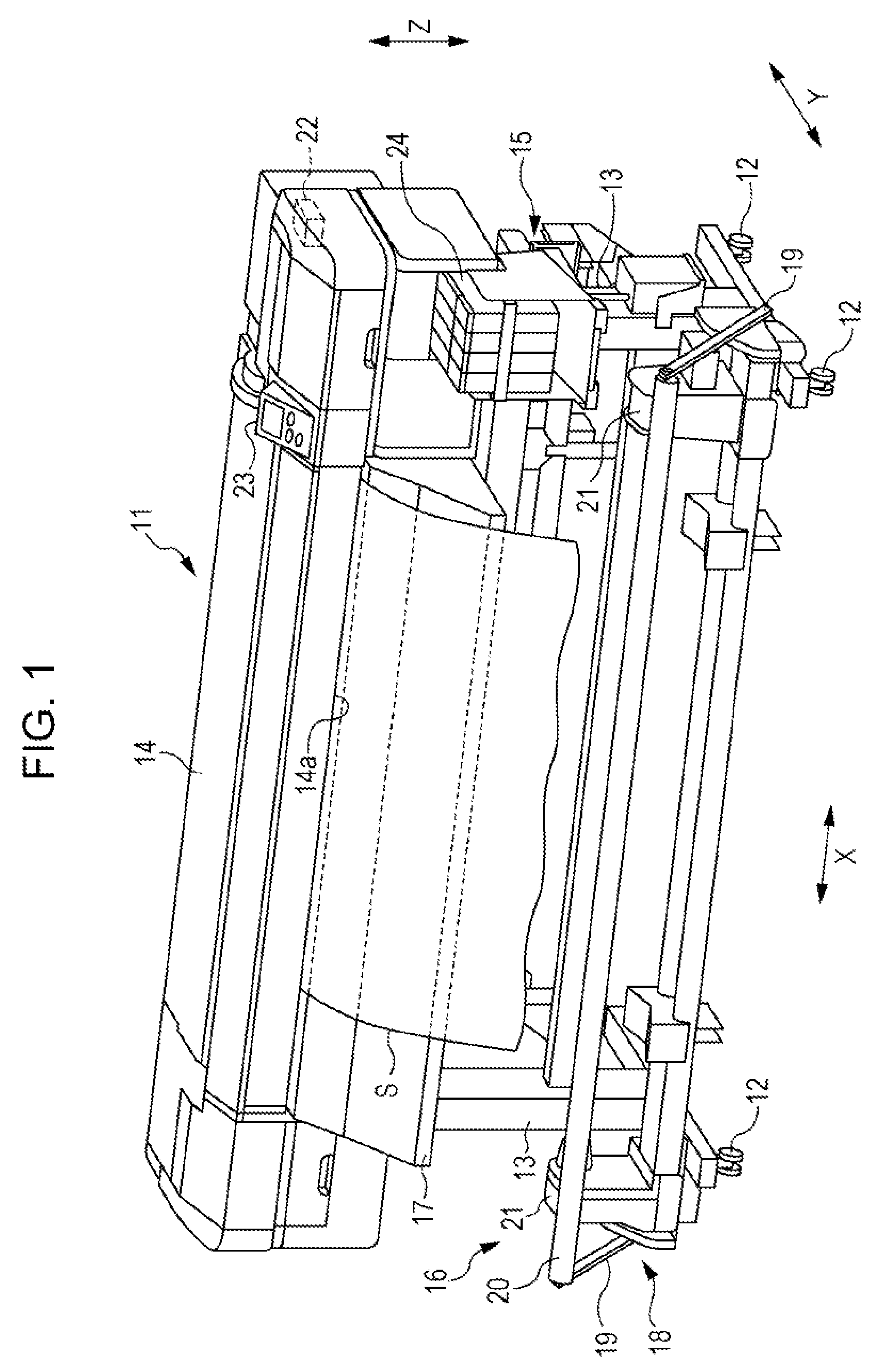
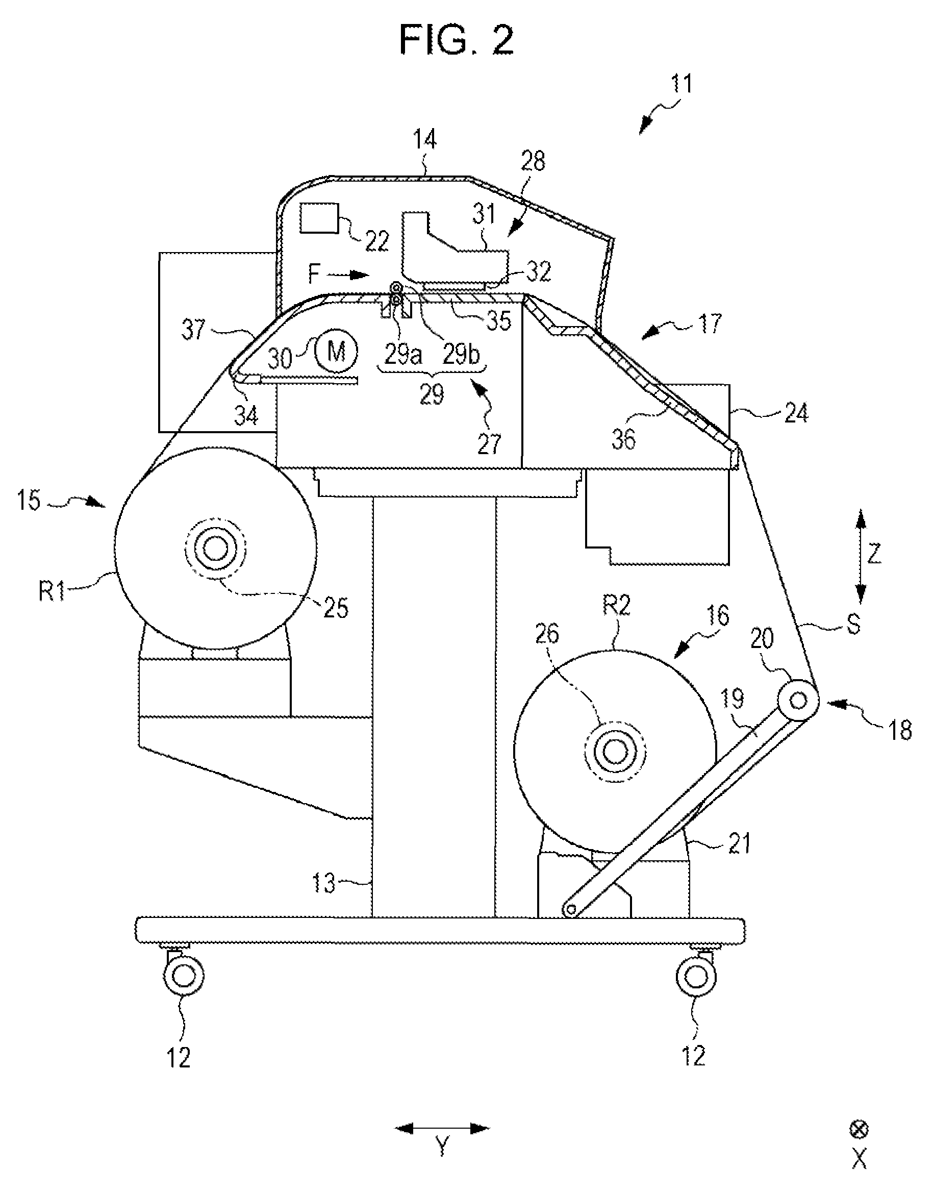
[0030]As illustrated in FIG. 1, a recording apparatus 11 of the exemplary embodiment is a large format printer (LFP) that handles a long sheet (roll paper) S that is an example of a medium.

[0031]The recording apparatus 11 includes a pair of leg portions 13 that have wheels 12 attached thereto at the lower end of each leg portion 13 and a housing 14 mounted on the leg portions 13. Note that in the exemplary embodiment, a width direction X denotes a longitudinal direction of the housing 14 that intersects (orthogonal in the exemplary embodiment) an up-down direction Z extending in the direction of gravity. Furthermore, a front-rear direction Y denotes a direction that intersects (orthogonal in the exemplary embodiment) both the up-down direction Z and the width direction X.

[0032]A feeding unit 15 that feeds a sheet S towards the housing 14 side is ...


PUM


Abstract

A transporting apparatus includes a pair of transport rollers that transport a medium along a transport path that extends in a transport direction, a medium supporting section that supports the medium at a portion downstream of the pair of transport rollers in the transport direction, a supporting projection that supports the medium at a portion downstream of the medium supporting section in the transport direction, the medium being supported at an upstream portion in the transport direction by the medium supporting section, and a guide portion that is arranged at a position downstream of the medium supporting section in the transport direction and upstream of the supporting projection in the transport direction, the guide portion forming a concavity in the transport path with respect to the medium supporting section and the supporting projection.

Description

BACKGROUND[0001]1. Technical Field[0002]The present invention relates to a transporting apparatus that transports a medium and to a recording apparatus that is provided with the transporting apparatus.[0003]2. Related Art[0004]As an example of a recording apparatus, there is an ink jet printer that performs printing by ejecting ink onto a medium such as roll paper. Among such printers, there is a printer in which a support member and a heater are arranged along a transport path extending from a recording unit, which performs printing, to a point where the printed sheet (roll paper) is wound. The support member has a curved support surface that applies tension to the sheet. The heater heats and dries a printed surface of the sheet. Moreover, the support member contributes to transmitting the heat of the heater to the sheet and to stretching out wrinkles of the sheet to be wound (see JP-A-2012-139822, for example).[0005]It is preferable that, not limited to when the sheet is heated by...

Claims


Application Information

Patent Timeline
Patent Type & Authority Patents(United States)
IPC IPC(8): B41J2/01B65H5/00B65H23/04B41J11/00B41J15/04B41J29/38
CPCB41J11/0005B41J15/046B65H23/04B65H2404/5214B65H2515/716B65H2515/842B65H2801/36B65H2515/70B65H2515/84
Inventor ISHIKAWA, AKIRAMIYAZAKI, KENICHI
Owner SEIKO EPSON CORP
Learn More