
Battery-operated welding and/or cutting device and a cooling profile

a battery-operated welding and/or cutting device technology, which is applied in the direction of welding devices, soldering devices, manufacturing tools, etc., can solve the problems of limiting the operation and the operating radius, not revealing the cooling of the battery, and no space in the device for proper cooling means, so as to achieve efficient conductivity and keep the size of the welding device compact

Active Publication Date: 2016-04-12
KEMPPI OY
View PDF10 Cites 1 Cited by
  • Summary
  • Abstract
  • Description
  • Claims
  • Application Information

AI Technical Summary

Benefits of technology

This solution effectively extends the operational time of the device, reduces fire safety risks, and maintains a compact size by efficiently conducting heat away from the battery cells, ensuring prolonged battery life and safe operation.

Problems solved by technology

Thus, the welding device is then easy to take along, but at the work location proper, there will always be a connection by cable to a power supply, which limits the operation and the operating radius.
However, the publication does not disclose any cooling of the batteries.
A problem in battery-operated devices, and particularly in welding and / or cutting devices requiring large momentary battery power, is the positioning of the batteries in the device in such a way that the heat produced by them would not cause problems to the device, the battery itself, nor to the user of the device.
On the other hand, a problem is also, that a battery-operated welding and / or cutting device should be as small as possible, in order to being easily portable, and then there is no space for proper cooling means in the device.
As batteries heat excessively, their lifetime is reduced, and then they have to be replaced sooner There may also be problems in regard to fire safety, since some battery chemistry is unstable when heated.
Then the batteries will be located close to each other in the device causing local heating in the device lacking proper cooling.
As the batteries heat up, the heat is transferred into their vicinity, and then also the device itself may get hot causing damage to the structures or indirectly causing a skin burn to the user of the device.

Method used


Image

  • Battery-operated welding and/or cutting device and a cooling profile
  • Battery-operated welding and/or cutting device and a cooling profile
  • Battery-operated welding and/or cutting device and a cooling profile

Examples


Embodiment Construction

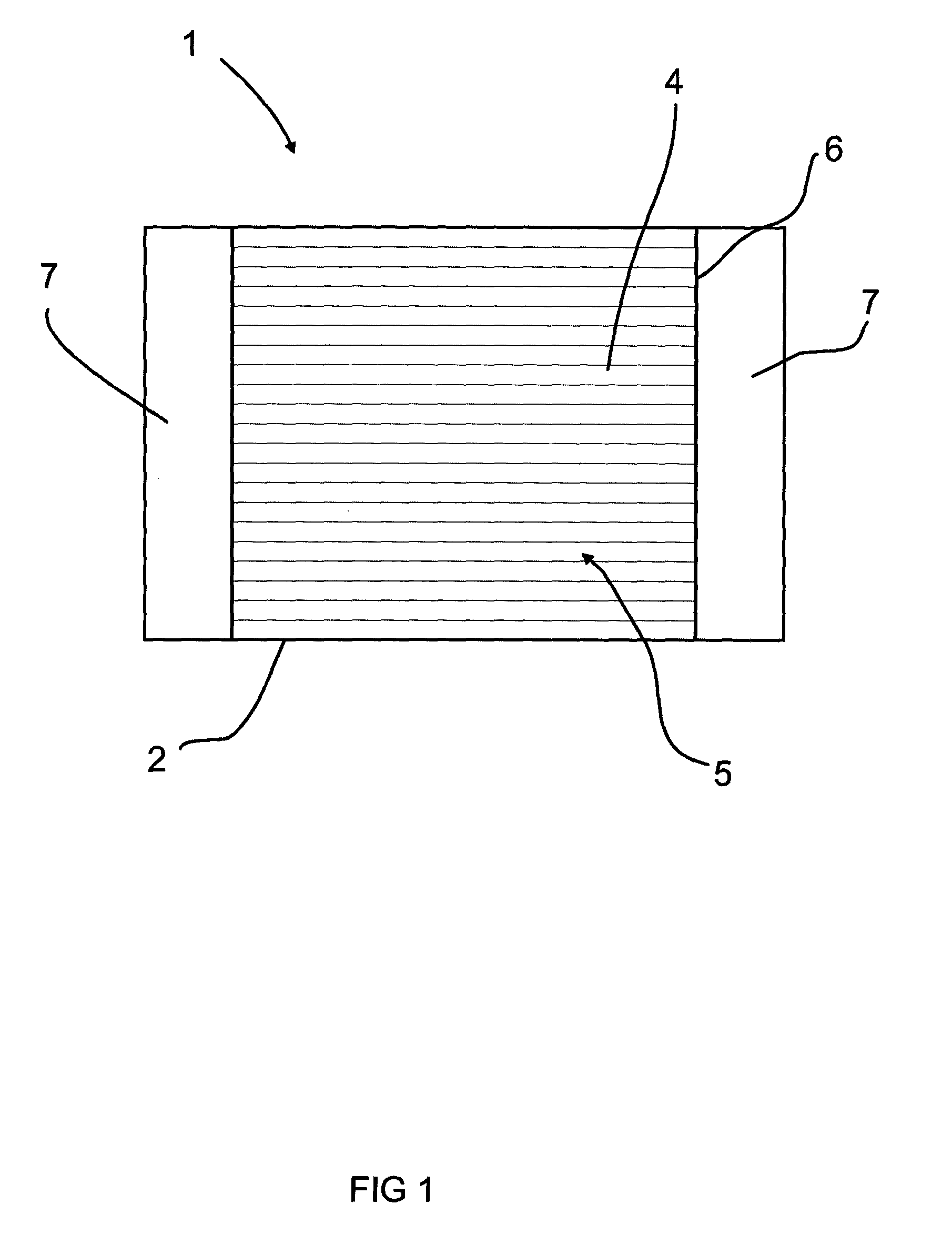
[0038]FIG. 1 shows a battery-operated welding and / or cutting device 1 comprising a cooling profile 4 serving as a frame 2 of the device 1, into which cooling profile 4 one or more battery cells (not shown in the Figure) have been provided. In this example, the cooling profile comprises two end surfaces 6, at both of which a cover structure 7 has been attachably provided. These cover structures 7 protect welding device components and / or welding additives as well as the connections of the battery cells being located between the cooling profile 4 and a cover structure 7. The outer surface 5 of the cooling profile 4 serves as the outer surface of the device 1, whereby the battery cells inserted in the cooling profile 4 deliver heat directly to the ambient air via the outer surface 5 of the cooling profile 4.

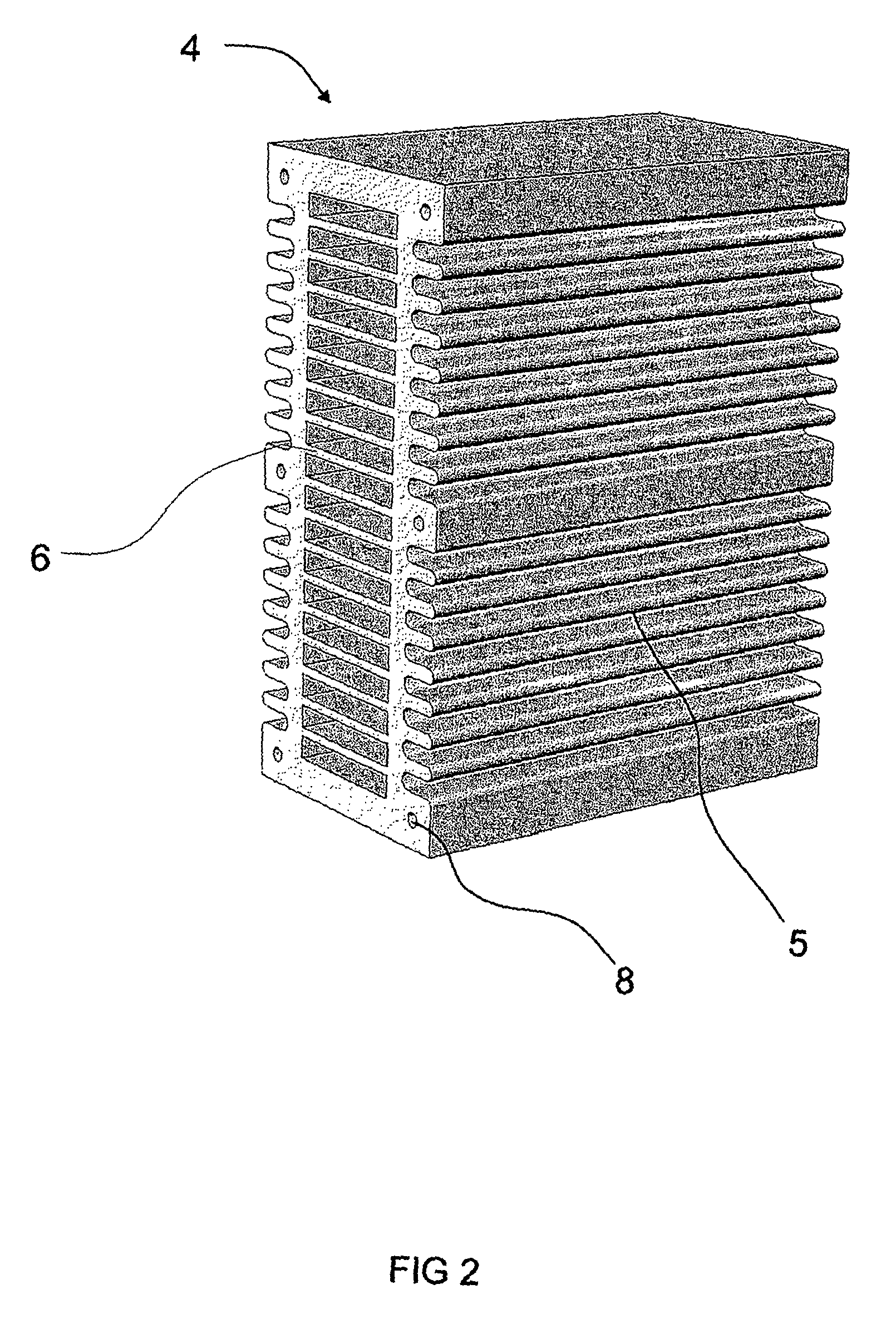
[0039]FIG. 2 shows a preferable embodiment of a cooling profile 4 according to the invention, into which cooling profile 4 at least one battery cell (not shown in the Figure) can be ...


PUM

PropertyMeasurementUnit
currentaaaaaaaaaa
angleaaaaaaaaaa
angleaaaaaaaaaa

Abstract

The object of the invention is a battery-operated welding and / or cutting device including a frame and at least one battery cell. The frame includes a cooling profile having an outer surface, which is in direct contact with the air surrounding the device. The cooling profile is provided to accommodate at least one battery cell, such that the cooling profile at least partly surrounds the battery cell in order to conduct heat from the battery cell to the cooling profile and, via the outer surface of the cooling profile, away from the device. The object of the invention is also a cooling profile.

Description

BACKGROUND OF THE INVENTION[0001]An object of the invention is a battery-operated welding and / or cutting device.[0002]An object of the invention is also a cooling profile.[0003]Previously known are various portable welding devices, which are easily carried along even in awkward working locations, These portable welding devices are powered by connecting them to an ordinary electric outlet or to a generator. Thus, the welding device is then easy to take along, but at the work location proper, there will always be a connection by cable to a power supply, which limits the operation and the operating radius.[0004]Previously known are also some battery-operated welding devices. Such battery-operated welding devices are disclosed in the publications WO 2009 / 029360 A1 and EP 1 852 206 A2.[0005]From the publication WO 2009 / 029360 A1, a battery-operated welding device is known, which is provided in a trunk-like case such, that the welding device is easily portable from one location to another...

Claims


Application Information

Patent Timeline
Patent Type & Authority Patents(United States)
IPC IPC(8): B23K9/10H01M10/6551H01M10/613B23K37/00H01M10/6554H01M10/6235B23K9/32
CPCB23K37/003B23K9/10B23K9/1006B23K9/32B23K26/702B23K26/703H01M10/613H01M10/6235H01M10/6551H01M10/6554B23K20/26B23K37/00Y02E60/10B23K9/1081
Inventor JOKINEN, PETTERITURUNEN, RAUNOALHONSALO, ILKKAKORHONEN, PETRI
Owner KEMPPI OY
Learn More