
Method for improving compression efficiency of distributed source coding using intra-band information

a distributed source and information technology, applied in the field of distributed source coding, can solve problems such as data compression, and achieve the effects of improving the compression efficiency, and improving the compression efficiency

Active Publication Date: 2016-04-05
MITSUBISHI ELECTRIC RES LAB INC
View PDF8 Cites 1 Cited by
  • Summary
  • Abstract
  • Description
  • Claims
  • Application Information

AI Technical Summary

Benefits of technology

[0010]The embodiments of the invention provide a method for improving the compression efficiency of distributed source coding (DSC) of an image by exploiting intra-band information to supplement the conventionally available side information. The embodiments also provide a method for reducing the syndrome coding rate.
[0012]This invention is based on the realization that, when a source signal is poorly correlated with the side information, intra-band correlations, i.e., correlations among the source bits are more useful for decoding than correlations between source and side information bits. This concept can be used to improve the compression efficiency of the distributed source coding. Note that this concept pertains to decoder based processing, and is therefore different also from conventional source coding where the correlations among source bits is performed at the decoder.
[0013]We describe two embodiments in which this concept is useful. The first embodiment involves using the correlation between the sign and magnitude bits of the source, to improve compression efficiency of distributed source coding. The second embodiment involves using the correlation between the causally decoded source transform coefficients for improving the compression efficiency.

Problems solved by technology

Typically, the number of syndrome bits is smaller than the number of bits in the encoded bitplane, thus resulting in data compression.

Method used


Image

  • Method for improving compression efficiency of distributed source coding using intra-band information
  • Method for improving compression efficiency of distributed source coding using intra-band information
  • Method for improving compression efficiency of distributed source coding using intra-band information

Examples


Embodiment Construction

Detailed Method Overview

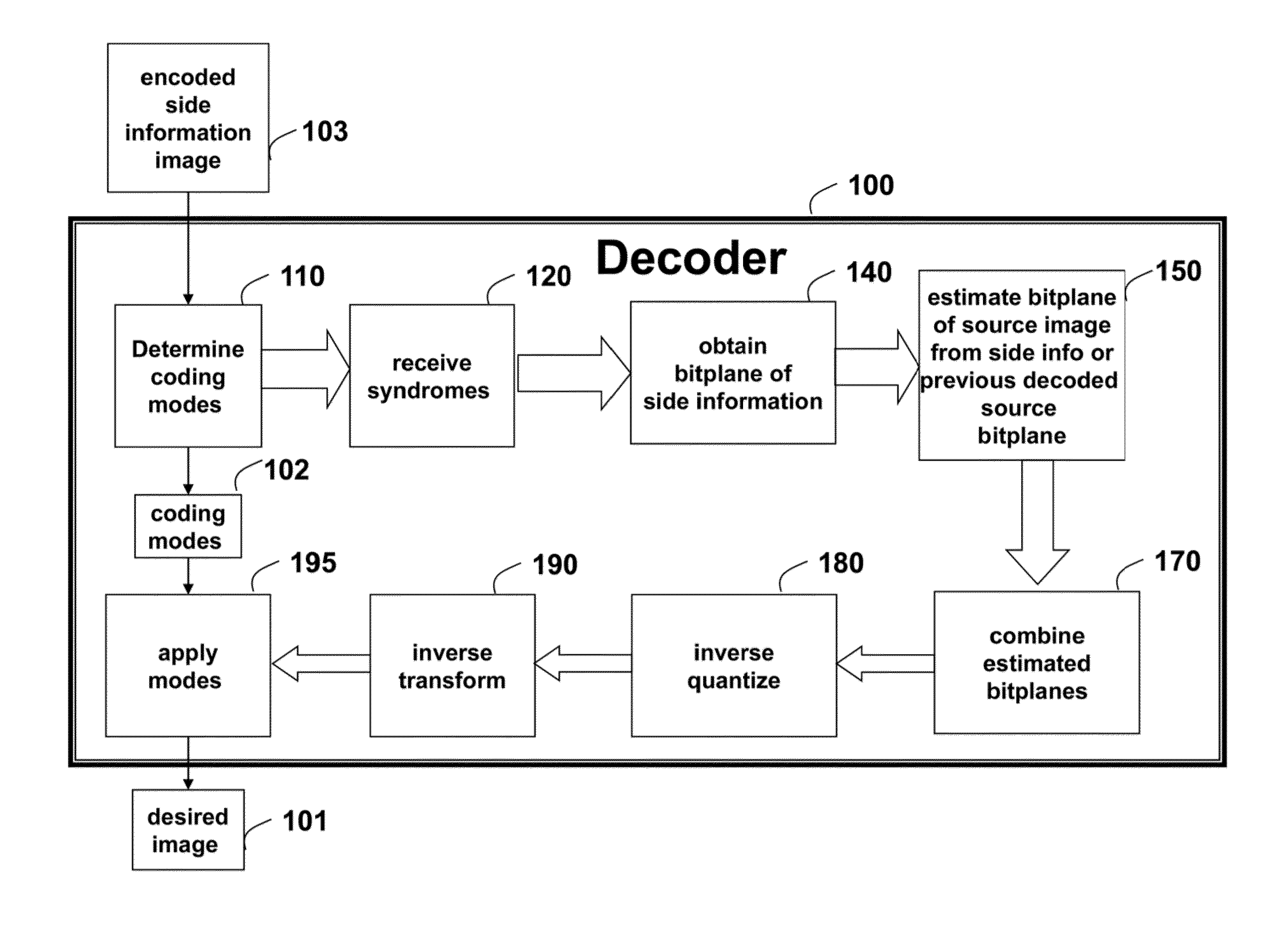
[0018]FIG. 1 is a flow diagram of a distributed source coding (DSC) method for recovering an estimate of a desired image 101 from an encoded input image. It is to be understood that certain coding modes 102 were chosen while encoding the input image. The method can operate in a decoder 100. The decoder can be implemented, in part, using a processor connected to memory and input / output interfaces connected by buses.

[0019]These coding modes are first determined 110 at the decoder. In some embodiments, the coding modes represent the intra and inter prediction coding modes inherited from encoded side information image 103. In other embodiments, the coding modes are independently determined from the input image, without consideration for the coding modes used in the side information image.

[0020]From an encoder, storage device or encoded bit stream, the decoder receives 120 syndrome bits, or parity bits applied to bitplanes of quantized transform coefficients of th...


PUM


Abstract

In a decoder, a desired image is estimated by first retrieving coding modes from an encoded side information image. For each bitplane in the encoded side information image, syndrome bits or parity bits are decoded to obtain an estimated bitplane of quantized transform coefficients of the desired image. A quantization and a transform are applied to a prediction residual obtained using the coding modes, wherein the decoding uses the quantized transform coefficients of the encoded side information image, and is based on previously decoded bitplanes in a causal neighborhood. The estimated bitplanes of quantized transform coefficients of the desired image are combined to produce combined bitplanes. Then, an inverse quantization, an inverse transform and a prediction based on the coding modes are applied to the combined bitplanes to recover the estimate of the desired image.

Description

RELATED APPLICATION[0001]This application is a continuation-in-part of U.S. application Ser. No. 14 / 036,385, “Distributed Source Coding using Prediction Modes Obtained from Side Information,” filed by Rane et al. on Sep. 25, 2013 and incorporated herein by reference. In the related application, a desired image is estimated according to coding modes, and syndrome or parity bits for each bitplane.FIELD OF THE INVENTION[0002]The invention relates generally to distributed source coding, and more particularly to distributed source coding applied to a set of correlated images.BACKGROUND OF THE INVENTION[0003]Distributed source coding (DSC) encodes correlated data from multiple sources that do not communicate with each other. By modeling a correlation between multiple sources in a decoder with channel codes, DSC shifts the computational complexity from an encoder to the decoder. Therefore, DSC is frequently used in applications with complexity-constrained and resource-constrained encoders,...

Claims


Application Information

Patent Timeline
Patent Type & Authority Patents(United States)
IPC IPC(8): G06K9/00H04N19/30H04N19/34H04N19/46
CPCH04N19/395H04N19/34H04N19/46
Inventor RANE, SHANTANUCOHEN, ROBERT A.VETRO, ANTHONYSUGIMOTO, KAZUO
Owner MITSUBISHI ELECTRIC RES LAB INC
Learn More