System and method for improving the performance of desiccant dehumidification equipment for low-humidity applications

a technology of desiccant dehumidifier and low-humidity, which is applied in the direction of lighting and heating apparatus, heating types, and separation processes, etc., can solve the problems of increased cooling load of process air conditioning equipment, increased size, cost and complexity, and dehumidifier may not be able to deliver air at a sufficiently low humidity

Active Publication Date: 2016-04-05
BRY AIR ASIA PVT
View PDF21 Cites 4 Cited by
  • Summary
  • Abstract
  • Description
  • Claims
  • Application Information

AI Technical Summary

Benefits of technology

[0021]Another object of the current invention is to achieve the above performance objectives with a unit and housing design that is simple and inexpensive to build and simple to control.

Problems solved by technology

This usually increases the cooling load on the process air conditioning equipment downstream of the dehumidifier.
Usually only one purge loop is used due to the increased size, cost and complexity of multiple purge loops.
Even with the performance enhancements described in FIGS. 4 and 5 (and the cited patents), the dehumidifier may still not be capable of delivering air at a sufficiently low humidity.
The significant disadvantages associated with the known art are the complexity of the systems provided, and the increased energy expense that is involved.
These disadvantages point out the need for a system that is not only functionally efficient but is also cost-effective.

Method used


Image

  • System and method for improving the performance of desiccant dehumidification equipment for low-humidity applications
  • System and method for improving the performance of desiccant dehumidification equipment for low-humidity applications
  • System and method for improving the performance of desiccant dehumidification equipment for low-humidity applications

Examples


Embodiment Construction

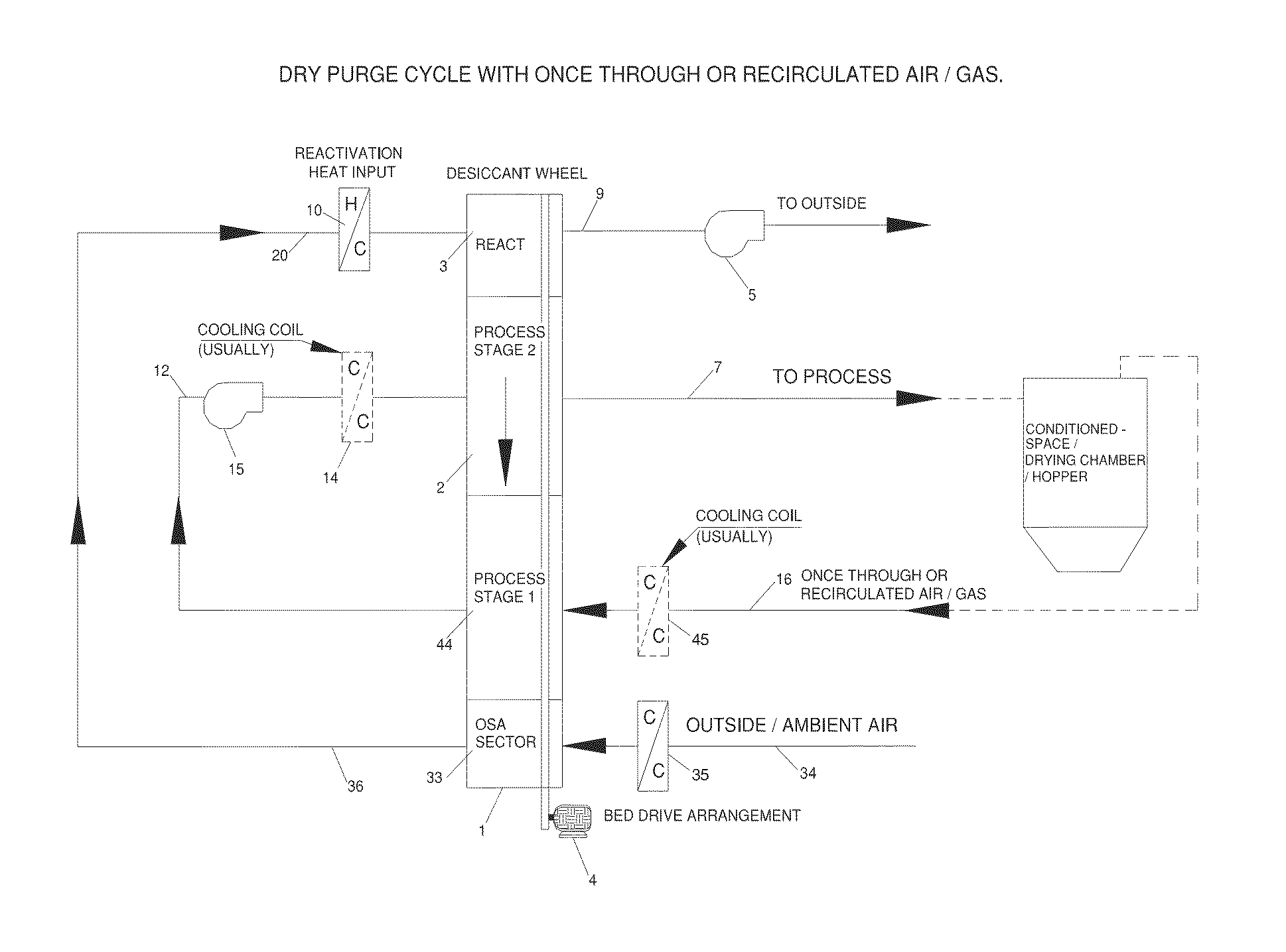
[0049]FIG. 7 is a schematic representation of the current invention configured to dehumidify a mixture of return (or recirculated) air 16 from a low-humidity space or process and outside air 36 for pressurization / makeup. The arrow inside the desiccant wheel indicates the sequence in which the wheel 1 rotates through the sectors, i.e. it rotates sequentially through the reactivation 3, process 2 and outside air 33 (or preconditioning) sector, and then back to the reactivation sector 3.

[0050]FIG. 7A is similar to FIG. 7 except a purge sector 17 has been added sequentially between the reactivation sector 3 and the process sector 2. The purge sector precools the desiccant media leaving the reactivation sector before it enters the process sector, improving the dehumidification performance of the unit and decreasing the reactivation heat carryover from the reactivation to the process sector. The purge discharge air 37 may be recycled to form at least a portion of the reactivation supply a...


PUM

PropertyMeasurementUnit
equilibrium relative humiditiesaaaaaaaaaa
humiditiesaaaaaaaaaa
adsorption capacityaaaaaaaaaa

Abstract

A method and apparatus for energy-efficient desiccant dehumidification of air or other gases to low humidity levels is disclosed. The method and apparatus includes a desiccant rotor (wheel) having more than one dehumidification zone or sector. Separate dehumidification sectors may be used to dehumidify separate air or gas streams, or they may be used to dehumidify a single air or gas stream by passing it through more than one sector. All or a portion of the discharge air or gas from a dehumidification sector is used for all or a portion of reactivation inlet air or gas prior to heating. The desiccant wheel may include more than one reactivation sector, with separate air or gas sources for each sector. The desiccant wheel may include a purge sector between the reactivation and dehumidification sectors to improve the thermal efficiency of the dehumidification process.

Description

FIELD OF THE INVENTION[0001]This invention relates generally to equipment that uses a solid desiccant material to remove moisture from air or other gases. It relates more specifically to thermally-reactivated desiccant dehumidifiers that use a rotating matrix or wheel containing a solid desiccant material to continuously dehumidify a stream of air or other gas. It relates more specifically still to thermally-reactivated desiccant dehumidifiers that are required to continuously deliver air or other gas to a space or process at very low humidity content, such as 0.1 grain moisture per pound of dry air (0.0143 grams moisture / Kg of dry air) or less. In these applications as much dry air as possible is typically re-circulated from the space or process back through the dehumidifier to minimize the moisture load on the dehumidifier, but some amount of air from a more humid source such as outside air or air from the surrounding plant is usually needed to pressurize the space or process to p...

Claims


Application Information

Patent Timeline
Patent Type & Authority Patents(United States)
IPC IPC(8): B01D53/06F24F3/14B01D53/26
CPCF24F3/1423B01D53/06B01D53/261B01D2251/302B01D2251/60B01D2253/106B01D2253/112B01D2253/116B01D2257/80B01D2258/06F24F2203/1088F24F2203/1092B01D53/26F24F3/14
Inventor PAHWA, DEEPAKSACHDEV, RAJANGRIFFITHS, WILLIAM CHARLESMALIK, KULDEEP SINGH
Owner BRY AIR ASIA PVT
Why Eureka
Try Eureka