Method of controlling the flow rate of a variable capacity hydraulic pump for a construction apparatus

a technology of variable capacity and hydraulic pump, which is applied in the direction of fluid coupling, rotary clutch, servomotor, etc., can solve the problems of difficult to ensure a more precise manipulability, shorten the control range of the manipulation lever b>1/b> by the user, and reduce the pressure loss, improve the fuel efficiency, and improve the effect of manipulability and safety

Active Publication Date: 2016-04-05
VOLVO CONSTR EQUIP AB
View PDF17 Cites 0 Cited by
  • Summary
  • Abstract
  • Description
  • Claims
  • Application Information

AI Technical Summary

Benefits of technology

[0034]In a state in which a preset value is determined which limits the maximum dischargeable flow rate of the hydraulic pump, the discharge flow rate of the hydraulic pump is controlled in proportion to the manipulation amount of the manipulation lever within a range that does not exceed the preset value so that a control range of the manipulation lever can be secured to improve manipulability and safety even during the lifting work of heavy materials. Further, in the case where a high load occurs during the work, a hydraulic fluid is discharged in at a state in which the open area of the spool (i.e., a spool for MCV) is widened, thereby reducing a pressure loss and thus improving a fuel efficiency.
[0034]In a state in which a preset value is determined which limits the maximum dischargeable flow rate of the hydraulic pump, the discharge flow rate of the hydraulic pump is controlled in proportion to the manipulation amount of the manipulation lever within a range that does not exceed the preset value so that a control range of the manipulation lever can be secured to improve manipulability and safety even during the lifting work of heavy materials. Further, in the case where a high load occurs during the work, a hydraulic fluid is discharged in at a state in which the open area of the spool (i.e., a spool for MCV) is widened, thereby reducing a pressure loss and thus improving a fuel efficiency.

Problems solved by technology

In the case where the discharge pressure of the hydraulic pump 3 is controlled by the above-mentioned method, i.e., the discharge pressure of the hydraulic pump 3 is controlled by a mechanical mechanism or an electronic control device to limit the torque or horsepower, if the discharge pressure of the hydraulic pump 3 is high, there occurs a problem in that the control range of the manipulation lever 1 by the user is shortened.
Particularly, even in the case where a more precise work is required such as the lifting work of heavy materials, the control range of the manipulation lever 1 is shortened, which makes it difficult to ensure a more precise manipulability.
Thus, there occurs a problem in that the control range (b) of the manipulation lever is relatively short as compared to a control range (a) of the manipulation lever as shown in FIG. 4, leading to a deterioration of manipulability.
As such, the control range in the case where the manipulation amount of the manipulation lever is 75% of maximum manipulation amount is shorter than that in the case where the manipulation amount of the manipulation lever is 50% of maximum manipulation amount, which makes it impossible to precisely manipulate the manipulation lever during the lifting work of heavy materials.

Method used


Image

  • Method of controlling the flow rate of a variable capacity hydraulic pump for a construction apparatus
  • Method of controlling the flow rate of a variable capacity hydraulic pump for a construction apparatus
  • Method of controlling the flow rate of a variable capacity hydraulic pump for a construction apparatus

Examples


Embodiment Construction

Technical Problems

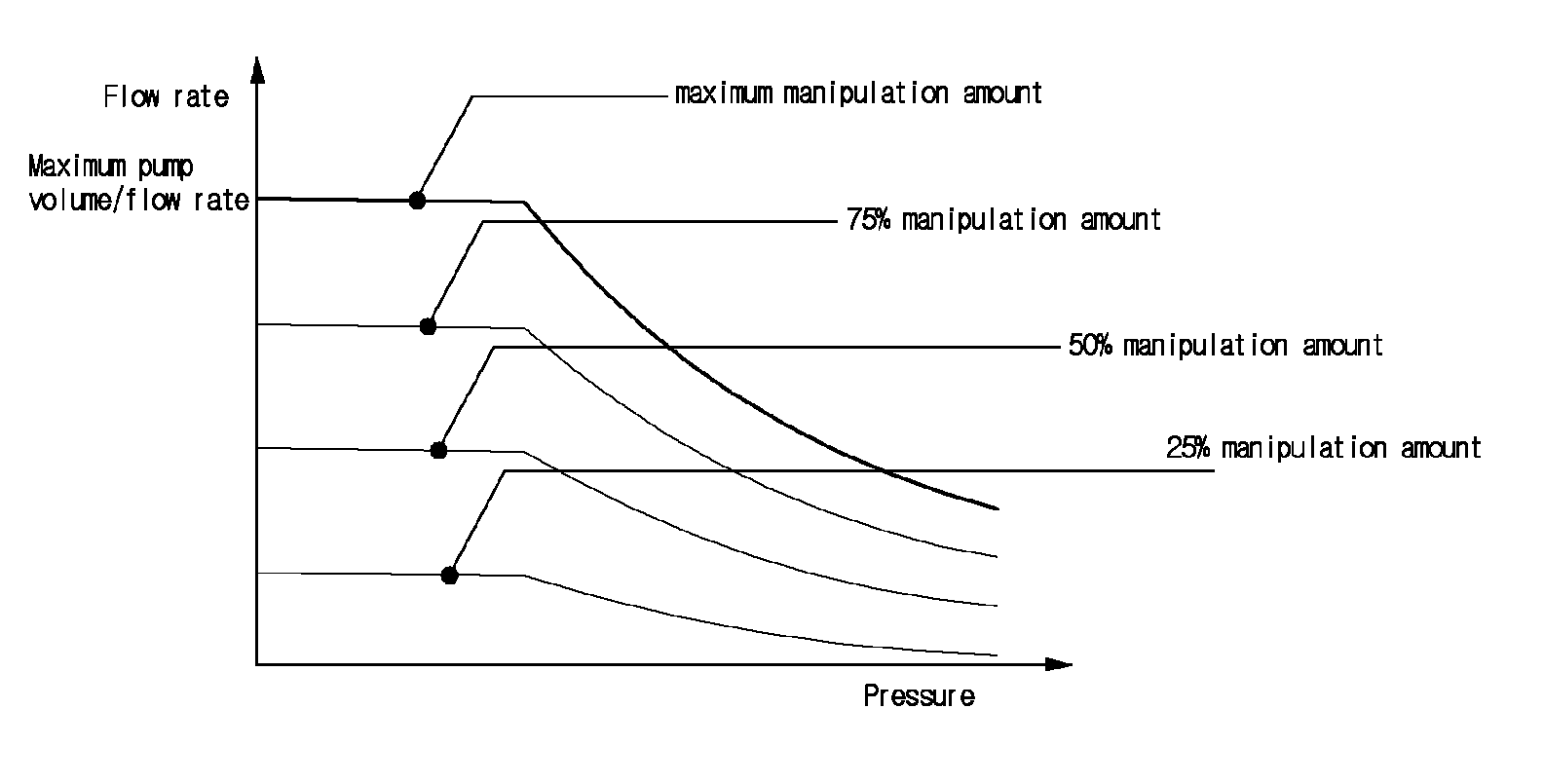
[0026]Accordingly, the present invention was made to solve the aforementioned problem occurring in the prior art, and it is an object of the present invention to provide a method of controlling a flow rate of a variable displacement hydraulic pump for a construction machine, in which in a state in which a preset value is determined which limits the maximum dischargeable flow rate of the hydraulic pump, the discharge flow rate of the hydraulic pump is controlled in proportion to the manipulation amount of the manipulation lever within a range that does not exceed the preset value so that a control range of the manipulation lever can be secured even in the case where a high load occurs during the work, thereby improving manipulability and safety.

Technical Solution

[0027]To accomplish the above object, in accordance with an embodiment of the present invention, there is provided a method of controlling a flow rate of a variable displacement hydraulic pump for a construc...


PUM


Abstract

Disclosed is a method of controlling the flow rate of a hydraulic pump, which controls the discharge flow rate in proportion to a manipulated amount of a manipulation lever operated by a user even when the discharge pressure of the hydraulic pump is varied. The method of controlling the flow rate of a variable capacity hydraulic pump for a construction apparatus according to the present invention includes: a first step of calculating the required flow rate of the variable capacity hydraulic pump according to a manipulated amount of a manipulation lever operated by a user; a second step of calculating the maximum discharge flow rate within a range equal to or less than a preset horsepower or torque of the variable capacity hydraulic pump corresponding to the pressure detected by a discharge pressure detecting sensor; and a third step of controlling the discharge flow rate of the variable capacity hydraulic pump in proportion to a manipulated amount of the manipulation lever within a range equal to or less than the maximum discharge flow rate set in the second step.

Description

FIELD OF THE INVENTION[0001]The present invention relates to a method of controlling a flow rate of a variable displacement hydraulic pump for a construction machine, in which a discharge flow rate of a hydraulic pump is controlled according to the manipulation amount of a manipulation lever (RCV) by a user. More particularly, the present invention relates to such a flow rate control method of a hydraulic pump, in which a discharge flow rate of the hydraulic pump can be controlled in proportional to the manipulation amount of a manipulation lever even when the discharge pressure of the hydraulic pump is changed.BACKGROUND OF THE INVENTION[0002]FIG. 1 is a schematic block diagram showing the configuration of a hydraulic system to which a method of controlling a flow rate of a variable displacement hydraulic pump for a construction machine in accordance with an embodiment of the present invention is applied.[0003]A conventional hydraulic system applied to a hydraulic construction mach...

Claims


Application Information

Patent Timeline
Patent Type & Authority Patents(United States)
IPC IPC(8): E02F9/22F15B9/04F15B11/042
CPCF15B9/04E02F9/2235E02F9/2285E02F9/2296F15B11/0423F15B2211/20546F15B2211/255F15B2211/6309F15B2211/6346F15B2211/6652F15B2211/6654F15B2211/6655E02F9/22F15B13/02F15B13/043
Inventor SHIN, HUNG-JU
Owner VOLVO CONSTR EQUIP AB
Why Eureka
Try Eureka