Spring wing controller

a controller and spring wing technology, applied in fluid-pressure devices for scotch-blocks, roads, transportation and packaging, etc., can solve the problems of noise, damage or wear to the spring wing and the frog, and the rate of closure is relatively slow, so as to minimize pressure spikes and oil cavitation

Active Publication Date: 2016-03-22
VOESTALPINE RAILWAY SYST NORTRAK LLC
View PDF22 Cites 0 Cited by
  • Summary
  • Abstract
  • Description
  • Claims
  • Application Information

AI Technical Summary

Benefits of technology

[0014]In one aspect, the invention comprises a controller for a spring wing that utilizes a floating piston rod carrying a fixed piston valve, and a free-moving piston head. The piston head is spring biased towards the valve. When the piston rod is actuated by the opening movement of the spring wing, the piston valve separates from the piston head briefly, allowing oil to flow in a relatively unrestricted manner and minimizing pressure spikes and oil cavitation within the controller. The spring movement urges the piston towards the valve, stopping the oil flow and helping to hold the spring wing in place. When the spring wing closes, the oil flow through the controller, which is adjustably set, allows the piston rod to move at a controlled rate, thereby controlling the closure rate of the spring wing.

Problems solved by technology

A common problem with spring wing frogs is that if the spring wing closes quickly, as compared to the speed of the passing train, it may close after each wheel or between cars, and then be forced open again for the next wheel.
In this case, the spring wing is subjected to a greater number of cycles in a given time frame, and is therefore susceptible to failure more rapidly.
That is, when the rail is open, the rate of closure is relatively slow, which prevents the rail from closing before the next set of car wheels passes.
However, a further consideration is that once the spring wing is released by the passing car wheel, it is biased to return to its original position and can do so very quickly, slamming against the side of the frog and causing noise and damage or wear to the spring wing and the frog.
However, hydraulic cylinders are susceptible to several potential problems.
Any small openings through which fluid is expected to pass may be subject to erosion and plugging due to contaminants in the fluid.
Components such as the metering jet are not replaceable, and may fail.
Further, such components, or any grooves or other orifices within the hydraulic cylinder, are not adjustable, so the closure speed and timing cannot be changed, for example for different train speed limits mandated by different locations.
Another potential drawback is hydraulic fluid leakage—if the fluid within the cylinder leaks, the cylinder will eventually have insufficient fluid and will not operate properly.
Even if there is sufficient fluid within the cylinder, hydraulic cylinders may still be susceptible to hydrolocking.
If the hydraulic fluid is unable to transit quickly enough through the check valve or any other openings, which tend to be relatively small and restrictive, the non-rod side of the cylinder will be too full of incompressible fluid, which prevents the rod from travelling far enough and causes it to buckle.
The resulting piston rod distortion results in misalignment of the check valves and causes a functional failure, if not a complete structural failure.

Method used


Image

  • Spring wing controller
  • Spring wing controller
  • Spring wing controller

Examples


Embodiment Construction

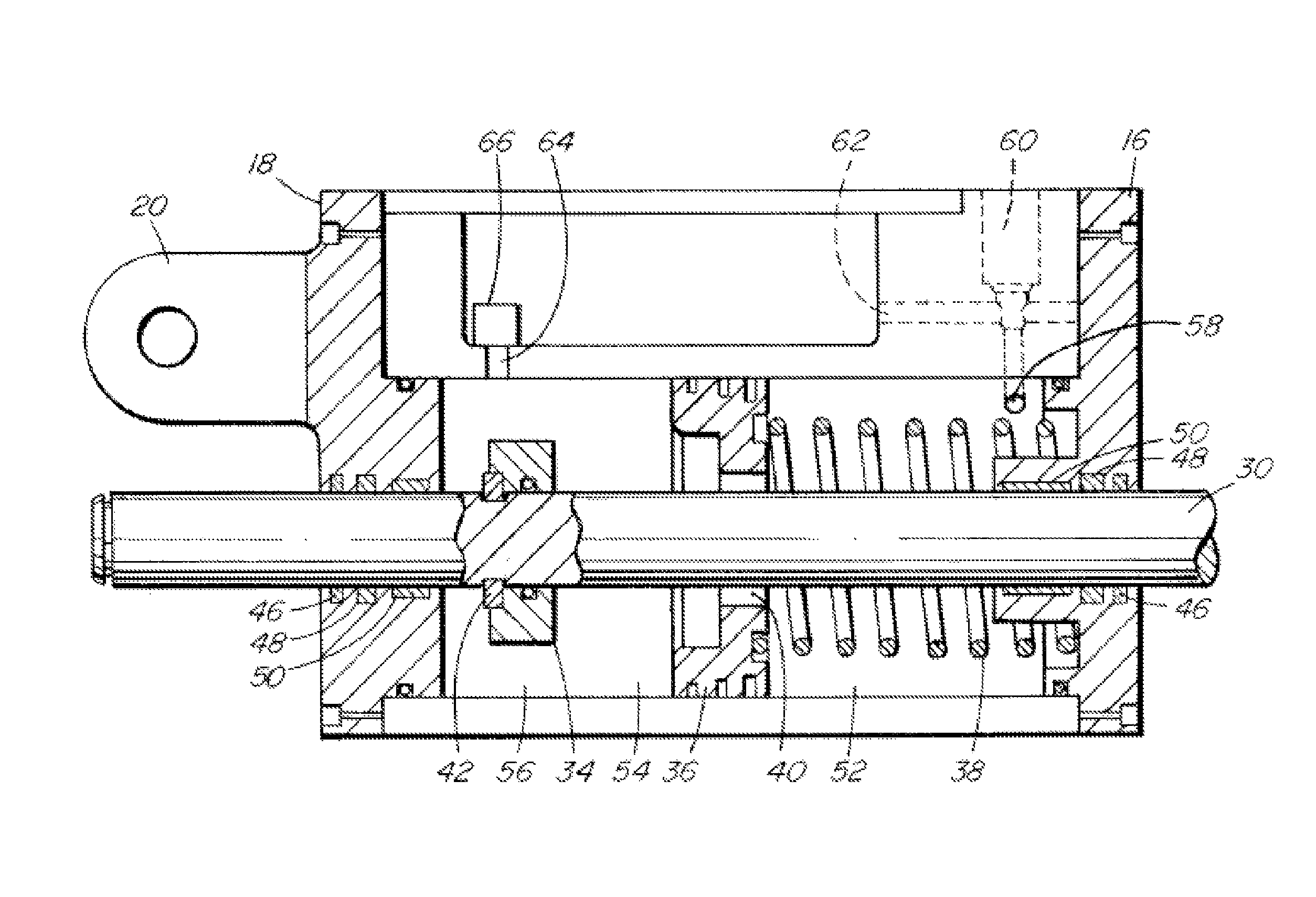
[0028]Referring to FIG. 1, the controller 10 of the invention comprises a casing 12 having a body 14 capped by front 16 and rear 18 end caps. A rear end cap 18 may be provided with a connecting mechanism 20 of any suitable configuration, to securely attach the controller 10 in place in the switch. In this context, the words “caps” does not necessarily require that the front and rear ends of the body 14 be separate pieces; the body 14 may be formed with integral front and / or rear portions. The body 14 may itself also be formed of one or more pieces.

[0029]An internal fluid reservoir 22 (shown only in FIG. 5), which is preferably covered by a removable cover 24 and provided with a fill valve 26, is also provided to hold a hydraulic fluid, such as oil or other suitable incompressible fluid. A fluid flow metering device, which is preferably externally accessible, such as via a cavity 28, is also provided to allow control and adjustment of the fluid flow through the controller 10, as will...


PUM


Abstract

A controller for a spring wing on a frog that utilizes a floating piston rod carrying a fixed piston valve and a free-moving piston head is provided. When the piston rod is actuated by the opening movement of the spring wing, the piston valve separates from the piston head briefly, allowing oil to flow through the piston head in a relatively unrestricted manner. The piston head is spring biased towards the piston valve; upon contact between the piston head and the piston valve, the oil flow through the piston head stops, helping to hold the spring wing in the open position. When the spring wing begins to close, the adjustable oil flow through the controller allows the piston rod to move at a controlled rate, thereby controlling the closure rate of the spring wing.

Description

FIELD OF THE INVENTION[0001]This invention relates to a device to control the movement of a spring wing. In particular, this invention relates to a device comprising a hydraulic system to control the movement of a spring wing on a frog.BACKGROUND OF THE INVENTION[0002]A frog is used in a railway where two rails cross over each other, to provide support for the wheels as they pass over the intersection. A spring wing or spring rail frog has a movable wing rail that is connected only at one end, such that it moves laterally away from the frog to provide a flangeway when a wheel of a passing car engages the spring wing rail. Examples of basic spring wing frogs are described in U.S. Pat. Nos. 4,624,428 and 4,637,578, both to Frank.[0003]A common problem with spring wing frogs is that if the spring wing closes quickly, as compared to the speed of the passing train, it may close after each wheel or between cars, and then be forced open again for the next wheel. In this case, the spring wi...

Claims


Application Information

Patent Timeline
Patent Type & Authority Patents(United States)
IPC IPC(8): B61L5/04E01B7/14
CPCB61L5/04E01B7/14
Inventor CLICK, GARYDUFFNER, BRENTSMITH, BRADLEYWEBB, MARTIN
Owner VOESTALPINE RAILWAY SYST NORTRAK LLC
Why Eureka
Try Eureka