
System and method for digital signal processing

a digital signal and audio signal technology, applied in the field of digital signal processing systems, can solve problems such as poor design of acoustics, and achieve the effects of improving sound presentation, constant rich output level, and widening presentation

Active Publication Date: 2016-03-08
BONGIOVI ACOUSTICS LLC
View PDF200 Cites 40 Cited by
  • Summary
  • Abstract
  • Description
  • Claims
  • Application Information

AI Technical Summary

Benefits of technology

The present invention provides a mobile audio device that can be used in a vehicle to produce studio-quality sound using the vehicle's existing speaker system. The device manipulates audio signals to compensate for volume differences and produces a constant output level of rich, full sound. The device can be used in any environment, regardless of the quality of the electronics and speakers used. The invention also seeks to improve sound presentation by processing audio signals outside the efficiency range of both the human ear and audio transducers. The device reduces the bass portion of the audio signal before compression and enhances it after compression to ensure a spectrum rich in bass tones and free of muffling effects. The device can be tuned to each vehicle and provides precision tuning for all 4 independently controlled channels. The device delivers about 200 watts of power and can play standard digital formats, satellite radio, and MP3 players. It also includes a remote control and a detachable faceplate.

Problems solved by technology

This also includes environments that are poorly designed with respect to acoustics, such as, without limitation, a traditional living room, the interior of vehicles and the like.

Method used


Image

  • System and method for digital signal processing
  • System and method for digital signal processing
  • System and method for digital signal processing

Examples


Embodiment Construction

[0052]It is to be understood that the present invention is not limited to the particular methodology, compounds, materials, manufacturing techniques, uses, and applications described herein, as these may vary. It is also to be understood that the terminology used herein is used for the purpose of describing particular embodiments only, and is not intended to limit the scope of the present invention. It must be noted that as used herein and in the appended embodiments, the singular forms “a,”“an,” and “the” include the plural reference unless the context clearly dictates otherwise. Thus, for example, a reference to “an audio device” is a reference to one or more audio devices and includes equivalents thereof known to those skilled in the art. Similarly, for another example, a reference to “a step” or “a means” is a reference to one or more steps or means and may include sub-steps and subservient means. All conjunctions used are to be understood in the most inclusive sense possible. T...


PUM


Abstract

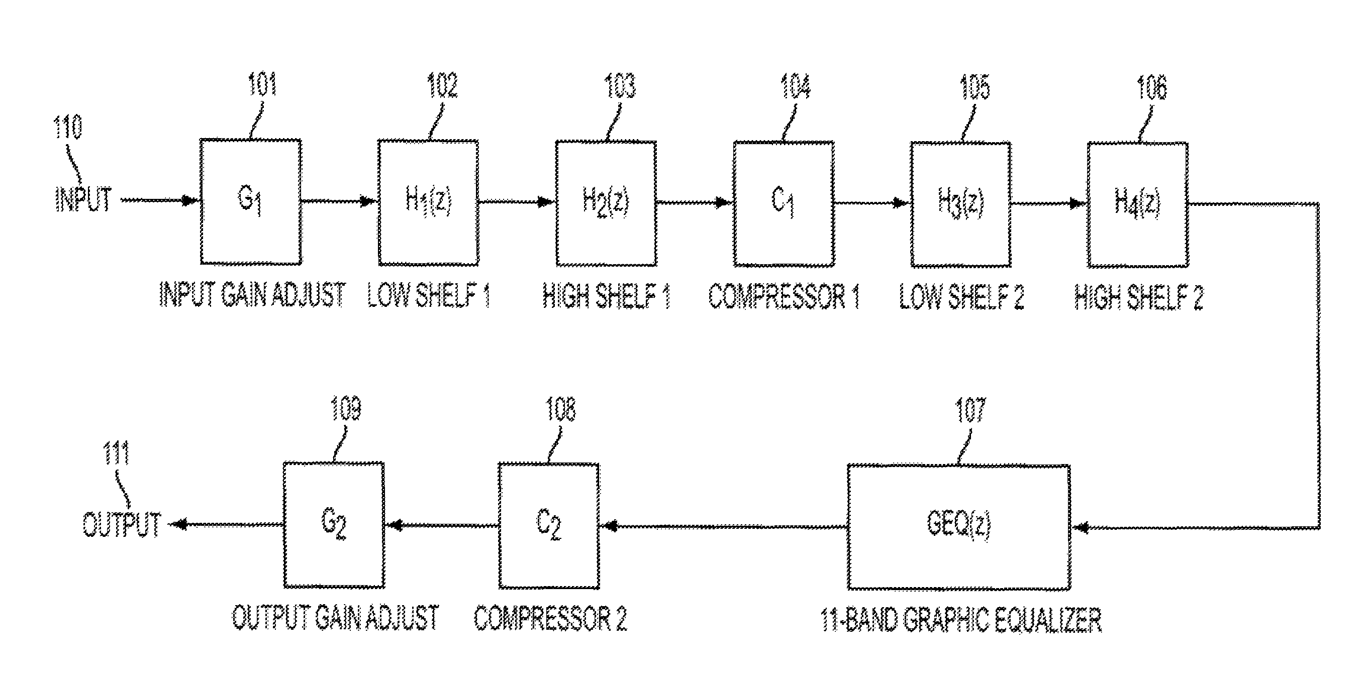
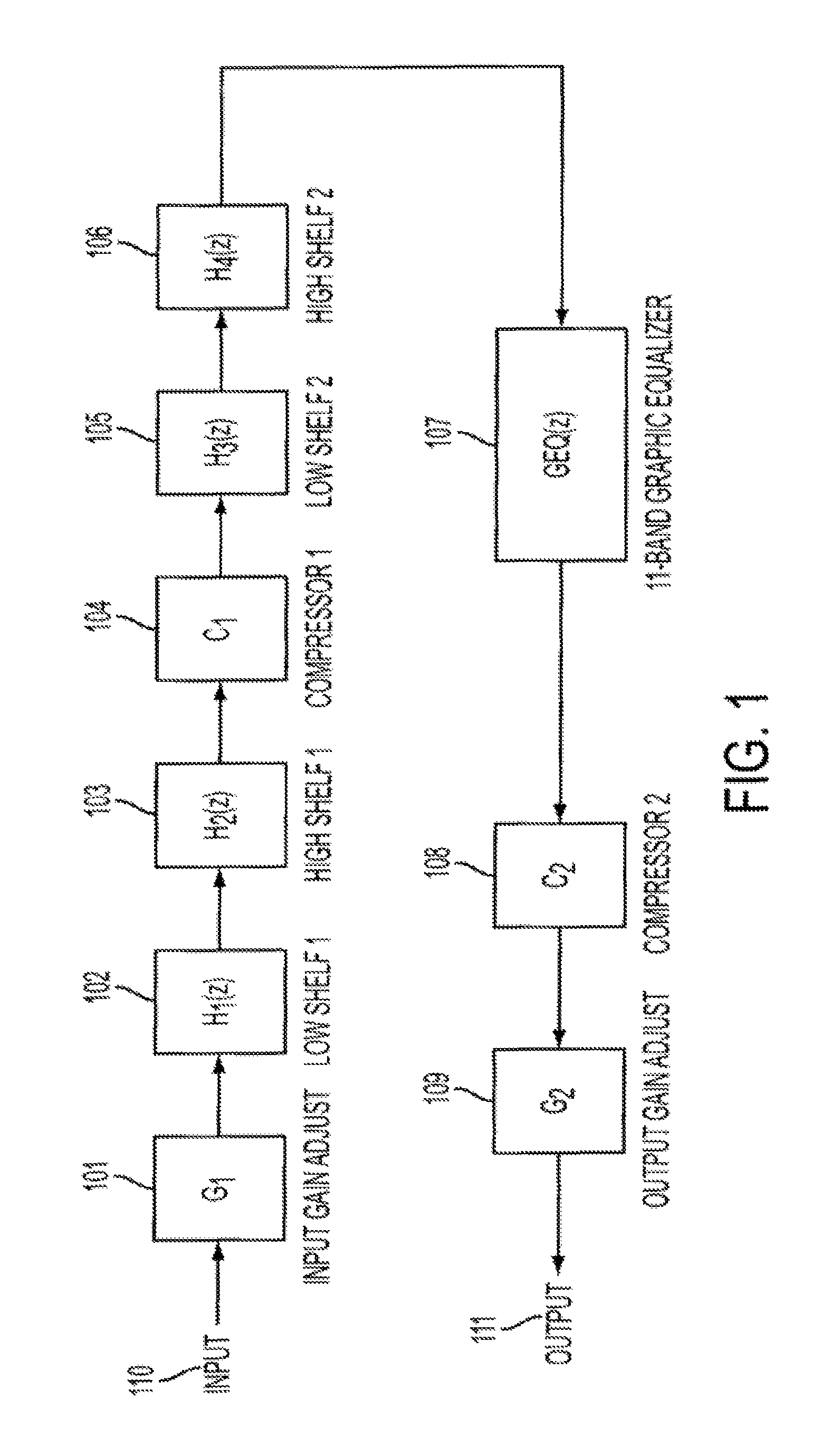
The present invention provides for methods and systems for digitally processing an audio signal and setting a peak signal threshold to a level that is determined to be safe, particularly for children or listeners with sensitive hearing. In various embodiments, a method comprises adjusting a gain of the signal based upon a received profile value minus a safety parameter, filtering the signal with a low shelf filter and / or high shelf filter, passing the signal through a first compressor that sets a peak threshold based upon the profile value minus the safety parameter, filtering the signal again with a low shelf filter and / or high shelf filter, processing the signal with a graphic equalizer, passing the signal through a second compressor that sets a peak threshold based upon the profile minus the safety parameter, and outputting the signal.

Description

CROSS-REFERENCE TO RELATED APPLICATIONS[0001]This application is a continuation-in-part of U.S. application Ser. No. 12 / 648,007 filed on Dec. 28, 2009, which matured into U.S. Pat. No. 8,565,449 on Oct. 22, 2013, (which is a continuation-in-part of U.S. application Ser. No. 11 / 947,301, filed Nov. 29, 2007, which matured into U.S. Pat. No. 8,160,274 on Apr. 17, 2012, which claims priority to U.S. Provisional Application No. 60 / 861,711 filed Nov. 30, 2006, and which is a continuation-in-part of U.S. application Ser. No. 11 / 703,216, filed Feb. 7, 2007, which claims priority to U.S. Provisional Application No. 60 / 765,722, filed Feb. 7, 2006). This application is also a continuation-in-part of U.S. application Ser. No. 12 / 048,885 filed on Mar. 14, 2008 which matured into U.S. Pat. No. 8,462,963 on Jun. 11, 2013, (which is a continuation-in-part of application Ser. No. 11 / 764,446 filed on Jun. 18, 2007, now U.S. Pat. No. 7,519,189, which issued on Apr. 14, 2009, which is a continuation of...

Claims


Application Information

Patent Timeline
Patent Type & Authority Patents(United States)
IPC IPC(8): H03G5/00H03G5/16
CPCH03G5/165H04L25/03012H04R1/005H04S1/007G10L21/0208G10L21/0232
Inventor BONGIOVI, ANTHONYFULLER, PHILLIPZELNIKER, GLENN
Owner BONGIOVI ACOUSTICS LLC
Learn More