
System for supplying energy

a technology for supplying energy and systems, applied in photovoltaic supports, emergency power supply arrangements, sustainable buildings, etc., can solve the problems of increasing initial installation costs and attracting ongoing power costs

Inactive Publication Date: 2016-03-01
TELEKOM MALAYSIA BERHAD
View PDF8 Cites 0 Cited by
  • Summary
  • Abstract
  • Description
  • Claims
  • Application Information

AI Technical Summary

Benefits of technology

The carbon collection system improves air quality in areas where the shelter is located. The communications system includes wireless and wired internet access points powered by solar energy. The dryer system is designed to dry passengers and their articles, particularly in rainy weather.

Problems solved by technology

Such a shelter will need to be connected to a power distribution network which will increase the initial cost of installation and attract ongoing power costs.

Method used


Image

  • System for supplying energy
  • System for supplying energy
  • System for supplying energy

Examples


Embodiment Construction

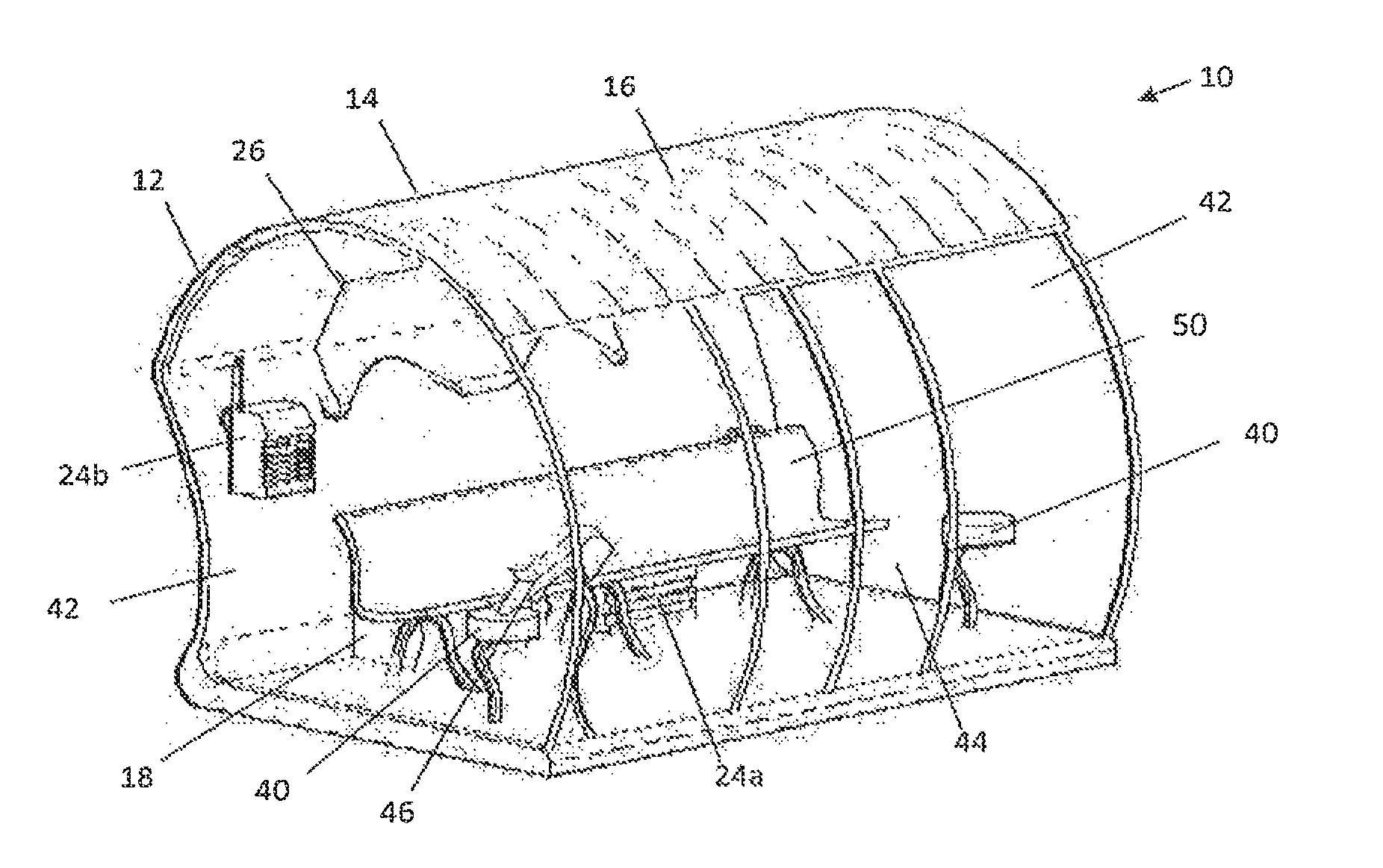
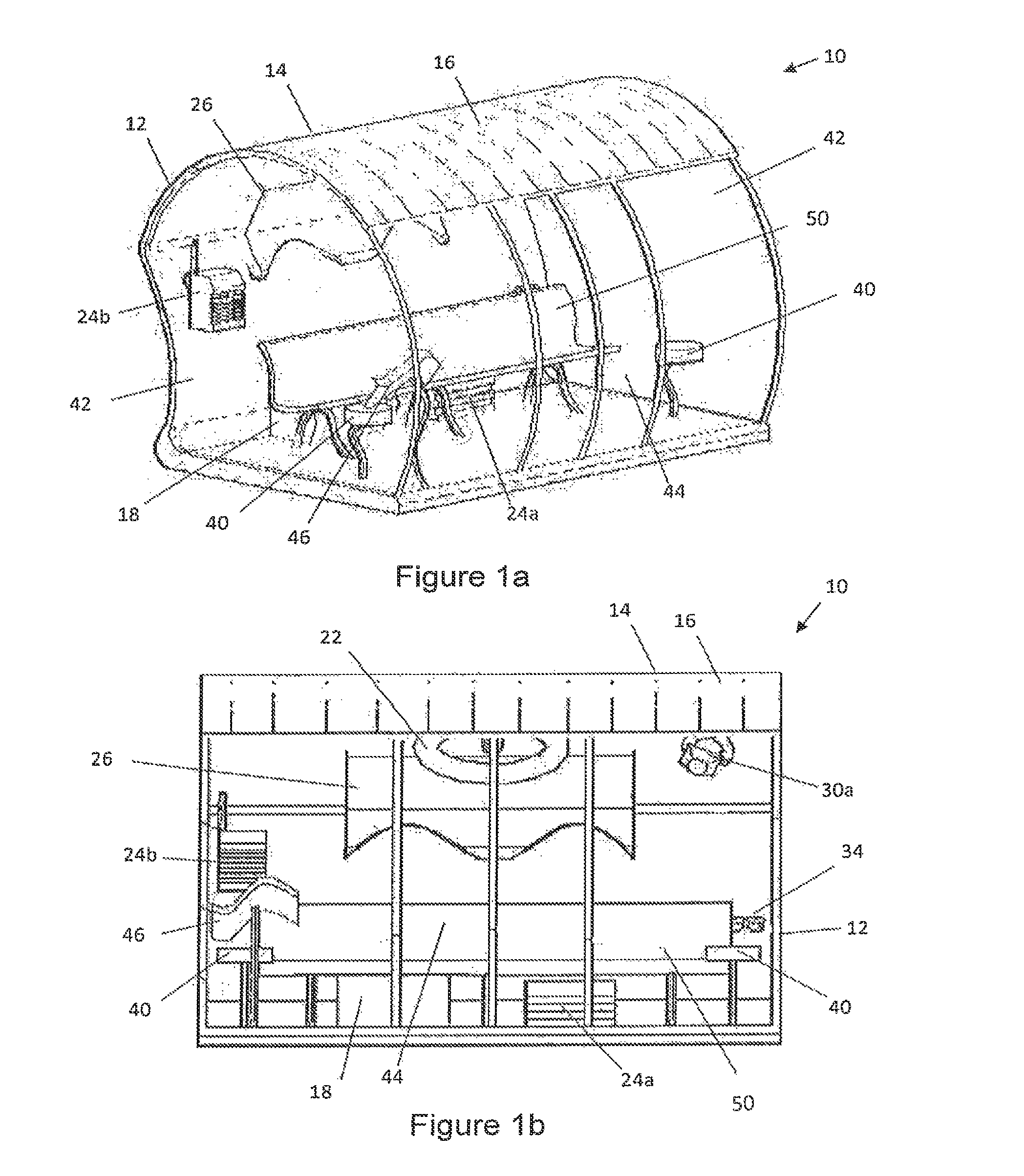
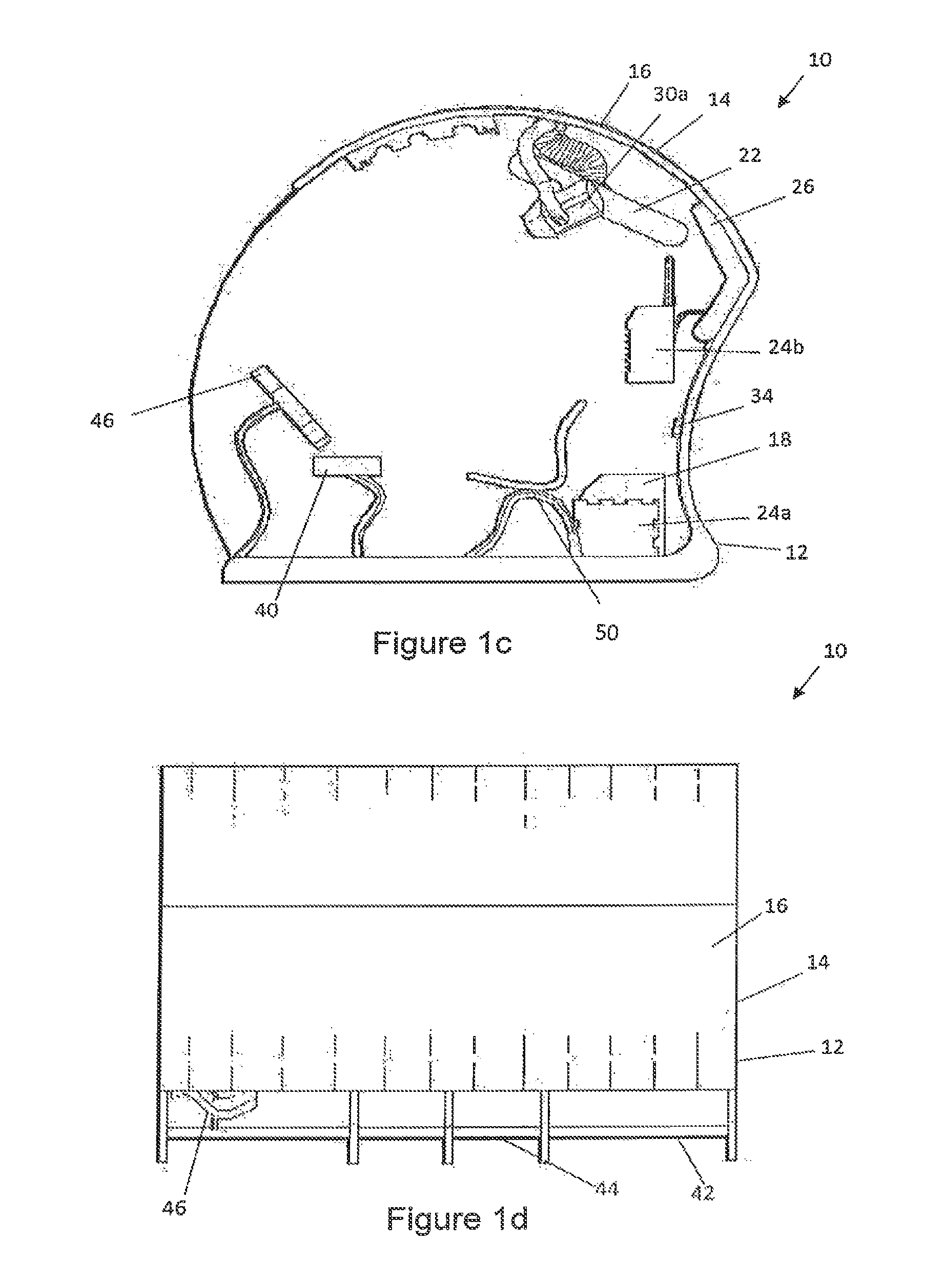
[0037]FIG. 1 shows a system 10 for supplying energy. The system 10 comprises a shelter 12 for passengers awaiting transport, the shelter having a roof portion 14. In this example the shelter 12 is a bus shelter, although it will be appreciated that the shelter 12 may be a train shelter, a tram shelter, a taxi shelter or any appropriate passenger shelter.

[0038]Photovoltaic cells 16 are disposed on the roof portion 14, the photovoltaic cells 16 being arranged to convert solar energy into electrical energy. The system 10 comprises an energy distribution system 18, shown schematically in FIG. 2, arranged to receive electrical energy from the photovoltaic cells 16 and to provide the electrical energy to electrically powered components of the system.

[0039]The system 10 may comprise any manner and variety of electrically powered components. In general, the electrically powered components will provide some form of use, benefit, or effect for or on the awaiting passengers. For example, the s...


PUM


Abstract

A system (10) for supplying energy is provided. The system (10) comprises a shelter (12) for a passenger awaiting transport. The shelter (12) has a roof portion (14) and photovoltaic cells (16) disposed on the roof portion (14). The photovoltaic cells (16) are arranged to convert solar energy into electrical energy. The system (10) also comprises an energy distribution system (18) arranged to receive electrical energy from the photovoltaic cells (16) and to provide the electrical energy to at least one electrically powered component (20, 22, 24, 26, 28, 30, 32, 34) of the system (10).

Description

[0001]This application claims the priority of Malaysian no. PI 2011006301 filed Dec. 28, 2011, hereby incorporated by reference.FIELD OF THE INVENTION[0002]The present invention relates to a system for supplying energy.BACKGROUND OF THE INVENTION[0003]Shelters that are provided for passengers awaiting transport, such as bus shelters, may provide lighting and other systems that require power. Such a shelter will need to be connected to a power distribution network which will increase the initial cost of installation and attract ongoing power costs.[0004]There is therefore a need for technological advancement.SUMMARY OF THE INVENTION[0005]In accordance with a first aspect of the present invention there is provided a system for supplying energy, the system comprising:[0006]a shelter for a passenger awaiting transport, the shelter having a roof portion;[0007]photovoltaic cells disposed on the roof portion, the photovoltaic cells being arranged to convert solar energy into electrical ene...

Claims


Application Information

Patent Timeline
Patent Type & Authority Patents(United States)
IPC IPC(8): H02J4/00E04H1/12H01L31/042
CPCH02J4/00E04H1/1211H02S20/00Y02E10/50Y10T307/25Y10T307/344Y02B10/12Y02B10/10
Inventor OMAR, NURUL, AFZANYUSOFF, ASHAARIYAHYA, MOHAMED, RAZMANDOLAH, ASBAN
Owner TELEKOM MALAYSIA BERHAD
Learn More