Eureka AIR delivers breakthrough ideas for toughest innovation challenges, trusted by R&D personnel around the world.

Organic light-emitting device

a light-emitting device and organic technology, applied in the direction of solid-state devices, electric lighting sources, electric light sources, etc., can solve the problem that the material is not suitable as a host material, and achieve the effects of low driving voltage, high t1 energy, and high emission efficiency

Active Publication Date: 2016-02-23
CANON KK
View PDF14 Cites 3 Cited by
  • Summary
  • Abstract
  • Description
  • Claims
  • Application Information

AI Technical Summary

Benefits of technology

[0008]The present invention provides an organic light-emitting device that uses a xanthone derivative having a high T1 energy and good electron injectability so that an organic light-emitting device having high emission efficiency and low driving voltage is provided and used as a blue or green phosphorescence-emitting device.
[0012]According to the present invention, an organic light-emitting device having high emission efficiency and low driving voltage can be provided by using a xanthone derivative having high T1 energy and good electron injectability.

Problems solved by technology

Since the excited triplet (T1) energy of this compound is low, this material is not suitable as a host material of an emission layer of a blue or green phosphorescence-emitting device or as a material for forming a carrier transport layer.

Method used

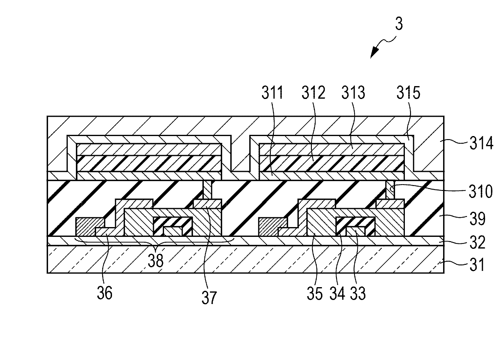
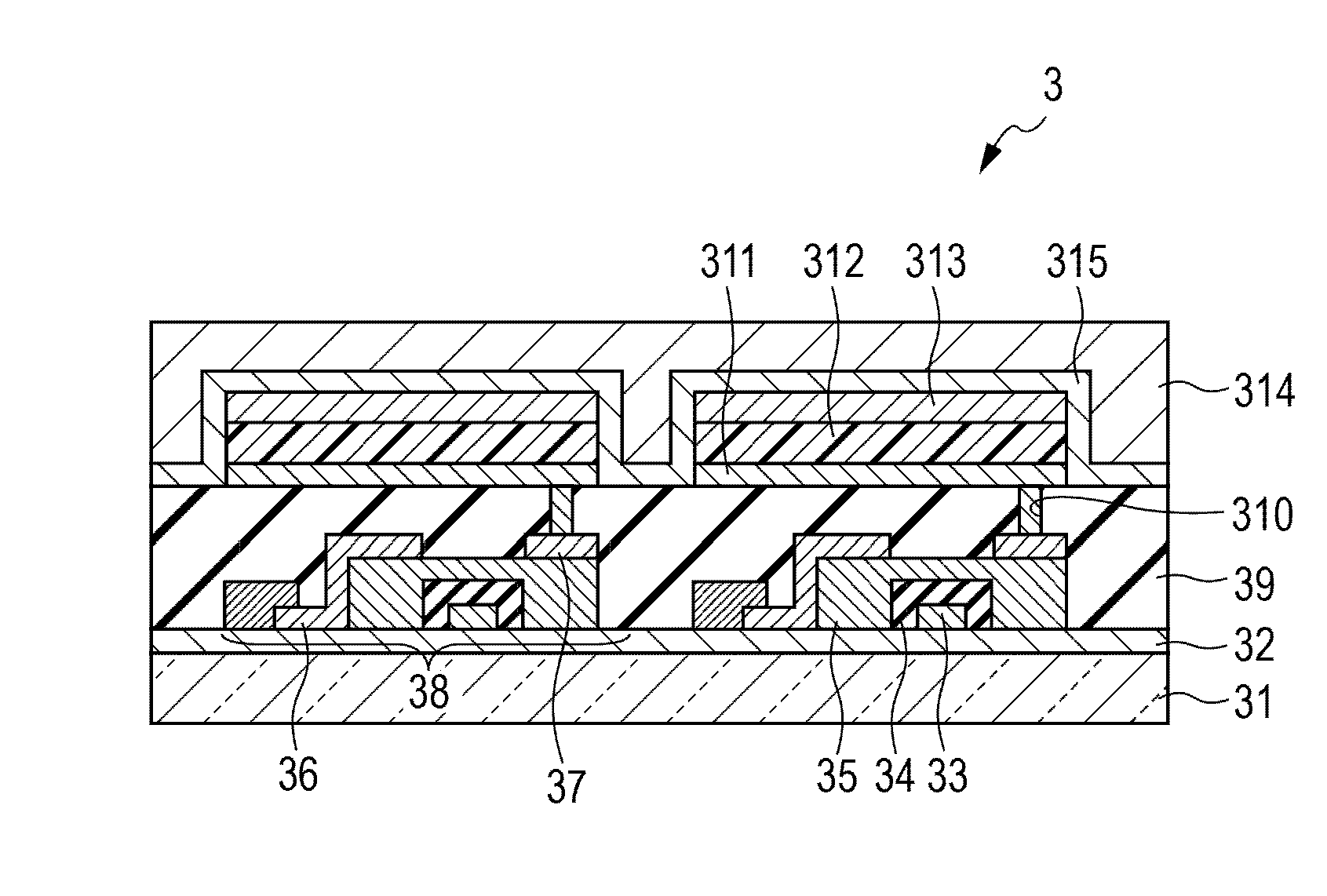

Image

  • Organic light-emitting device
  • Organic light-emitting device
  • Organic light-emitting device

Examples


example 1

Synthesis of Example Compound A-4

[0090]

[0091]The following reagents and solvents were placed in a 100 mL round-bottomed flask.[0092]Xanthone (Tokyo Chemical Industry Co., Ltd.): 5.0 g (26 mmol)[0093]Bromine: 16 g (102 mmol)[0094]Iodine: 50 mg (0.20 mmol)[0095]Acetic acid: 20 mL

[0096]The reaction solution was refluxed for 5 hours at 100° C. under heating and stirring in a nitrogen atmosphere. Upon completion of the reaction, chloroform and a saturated aqueous sodium sulfite solution were added to the reaction solution and stirring was continued until the color of bromine was lost. The organic layer was separated, washed with a saturated aqueous sodium carbonate solution, dried with magnesium sulfate, and filtered. The solvent in the filtrate was distilled away at a reduced pressure. The precipitated solid was purified with a silica gel column (toluene: 100%). As a result, 2.9 g (yield: 41%) of 2-bromoxanthone and 2.2 (yield: 25%) g of 2,7-dibromoxanthone were obtained.

[0097]The follo...

example 2

Synthesis of Example Compound A-5

[0110]

[0111]Example Compound A-5 was obtained as in Example 1 except that 4,4,5,5-tetramethyl-2-(4,4′-di-tert-butylbiphenyl-2-yl)-1,3,2-dioxaborolane used in Example 1 was replaced by 3-biphenylboronic acid.

[0112]M+ of this compound, 500.2, was confirmed by MALDI-TOF MS.

[0113]The structure of the compound was confirmed by 1H-NMR.

[0114]1H-NMR (CDCl3, 500 MHz) δ (ppm): 8.66 (2H, d), 8.06 (2H, dd), 7.91 (2H, bs), 7.72-7.66 (6H, m), 7.66-7.60 (4H, m), 7.57 (2H, t), 7.49 (4H, t), 7.39 (2H, t)

[0115]The T1 energy of Example Compound A-5 was measured as in Example 1. The T1 energy was 446 nm on a wavelength basis.

example 3

Synthesis of Example Compound A-7

[0116]

[0117]Example Compound A-7 was obtained as in Example 1 except that 4,4,5,5-tetramethyl-2-(4,4′-di-tert-butylbiphenyl-2-yl)-1,3,2-dioxaborolane used in Example 1 was replaced by 3,5-diphenylphenylboronic acid.

[0118]M+ of this compound, 652.2, was confirmed by MALDI-TOF MS.

[0119]The structure of the compound was confirmed by 1H-NMR.

[0120]1H-NMR (CDCl3, 500 MHz) δ (ppm): 8.72 (2H, d), 8.13 (2H, dd), 7.90 (4H, d), 7.84 (2H, dd), 7.74 (8H, d), 7.68 (2H, d), 7.51 (8H, t), 7.42 (4H, t)

[0121]The T1 energy of Example Compound A-7 was measured as in Example 1. The T1 energy was 447 nm on a wavelength basis.


PUM


Abstract

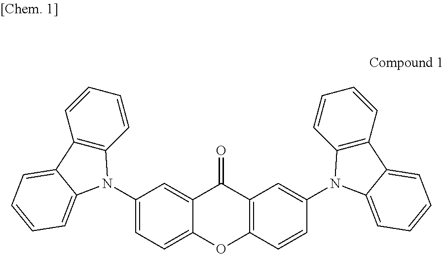
An organic light-emitting device that achieves highly efficient emission and low-voltage operation is provided. The organic light-emitting device contains a 9H-xanthen-9-one derivative.

Description

TECHNICAL FIELD[0001]The present invention relates to organic light-emitting devices.BACKGROUND ART[0002]An organic light-emitting device is a device that includes an anode, a cathode, and an organic compound layer interposed between the anode and the cathode. Holes and electrons injected from the respective electrodes of the organic light-emitting device are recombined in the organic compound layer to generate excitons and light is emitted as the excitons return to their ground state. The organic light-emitting device is also called an organic electroluminescent device or organic EL device. Recent years have seen remarkable advances in the field of organic light-emitting devices. Organic light-emitting devices offer low driving voltage, various emission wavelengths, rapid response, and small thickness and are light-weight.[0003]Phosphorescence-emitting devices are a type of device that includes an organic compound layer containing a phosphorescence-emitting material, with triplet e...

Claims


Application Information

Patent Timeline
Patent Type & Authority Patents(United States)
IPC IPC(8): H01L51/54H01L51/00H05B33/10H01L51/50
CPCH01L51/0073H01L51/0054H01L51/0058H01L51/0074H05B33/10C09K2211/1007C09K2211/1011C09K2211/1029C09K2211/1088C09K2211/1092H01L51/5016H01L51/5096H10K85/622H10K85/626H10K85/6576H10K85/6574H10K50/11H10K2101/10H10K50/18
Inventor HORIUCHI, TAKAYUKIKAMATANI, JUNYAMADA, NAOKIKISHINO, KENGOSAITOH, AKIHITO
Owner CANON KK
Why Eureka
Eureka Blog
Learn More