
Neutron detector

a neutron detector and detector technology, applied in the field of neutron detectors, can solve the problems of difficult to obtain sup>3, difficult to use it as a neutron image detector, and inferior neutron detection efficiency, so as to improve the neutron detection efficiency, improve the sensitivity of zns to the gamma ray, and achieve high detection efficiency.

Active Publication Date: 2016-02-23
JAPAN ATOMIC ENERGY AGENCY INDEPENDANT ADMINISTRATIVE CORP +1
View PDF8 Cites 2 Cited by
  • Summary
  • Abstract
  • Description
  • Claims
  • Application Information

AI Technical Summary

Benefits of technology

[0017]In the present invention, half transparent type neutron scintillator where a neutron detection body which includes a ZnS phosphor and a neutron converter material which contains 6Li or 10B is arranged is used to detect the neutron. ZnS phosphor mixed with 6LiF is used as a neutron scintillator for over 60 years because the sensitivity of ZnS to the gamma ray is low. However, there was a limit in thickening to improve the neutron detection efficiency because of half transparent type neutron scintillator.
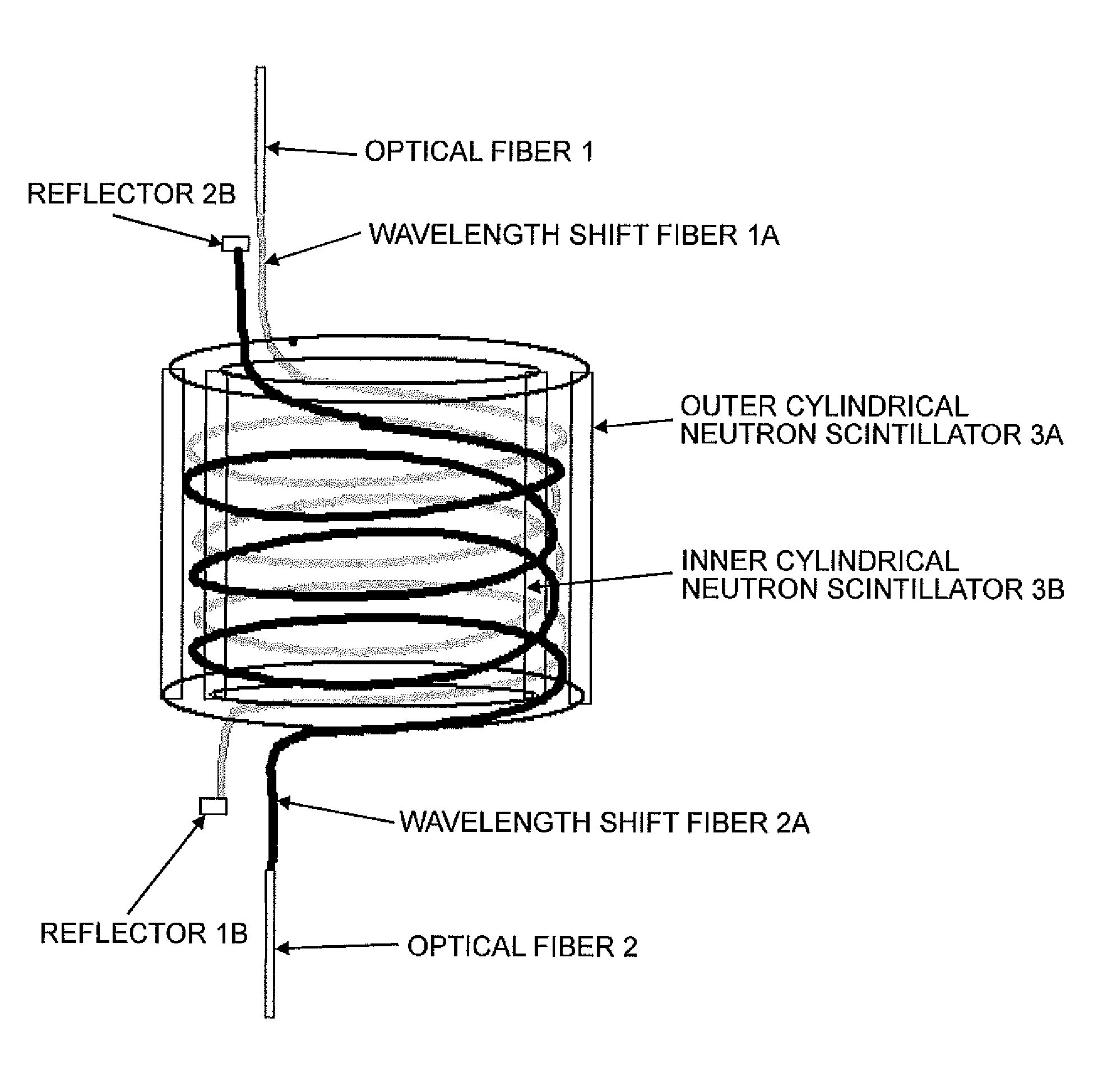
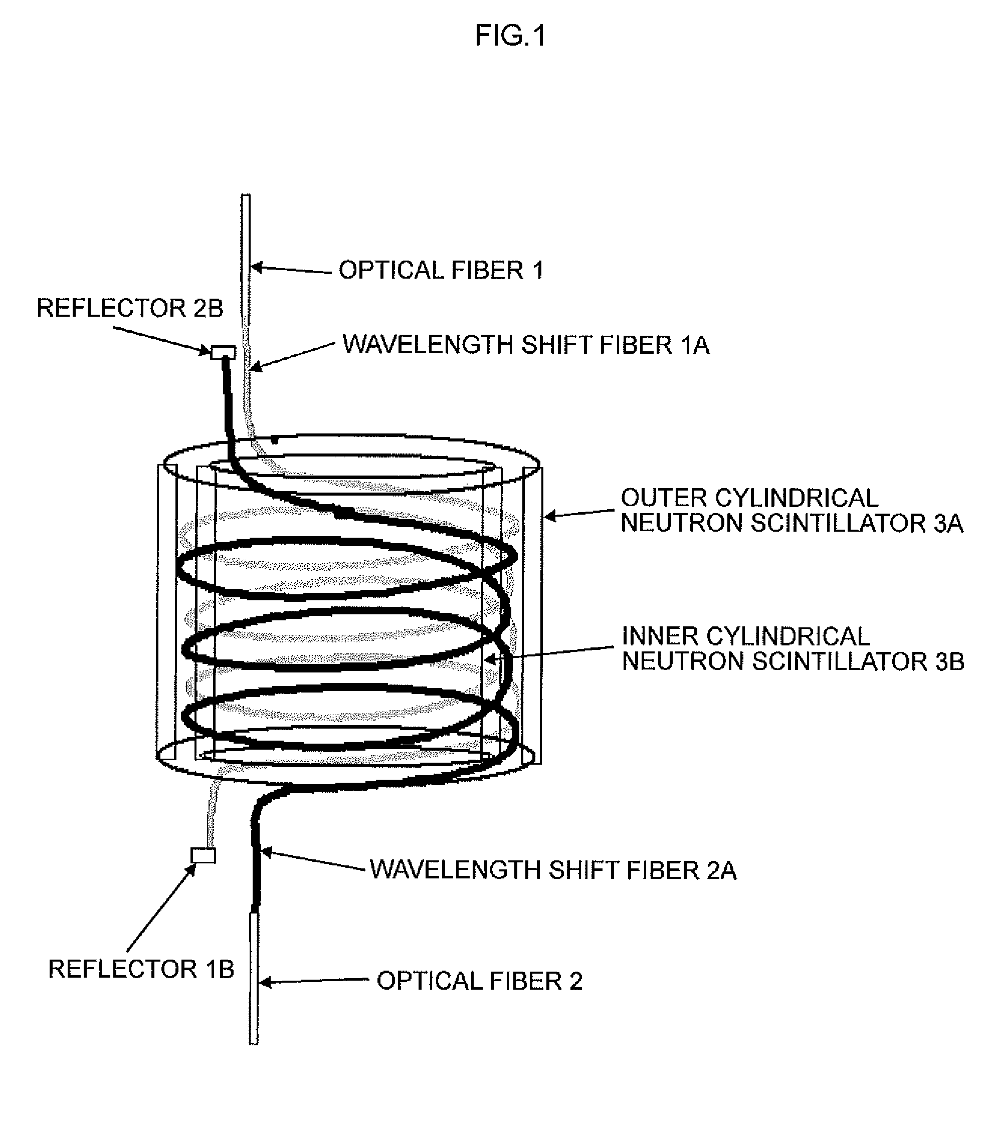
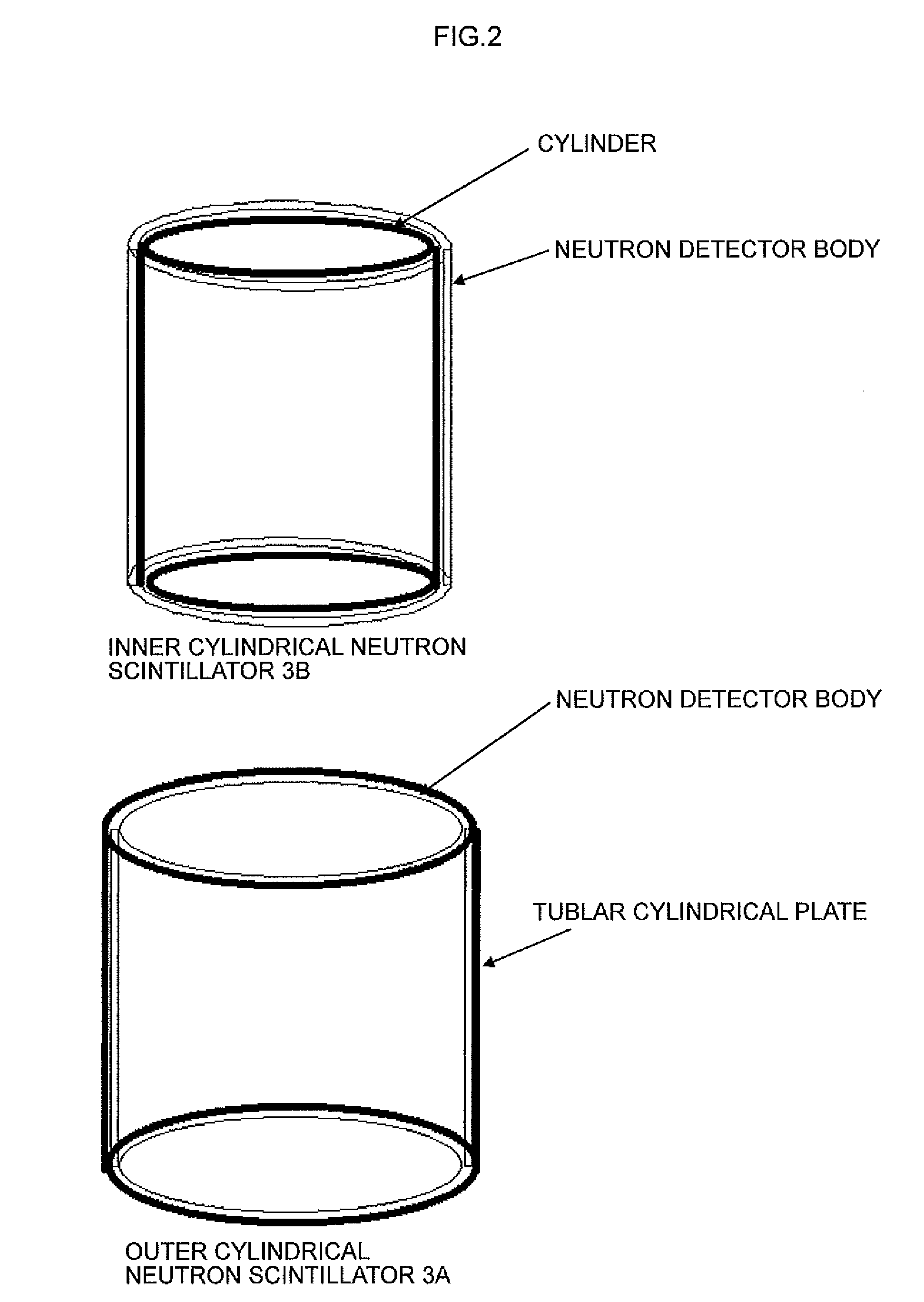
[0018]The neutron detecting element used in the present invention has the sandwich structure. That is, the neutron detecting element comprises: an inner cylindrical neutron scintillator where a neutron detection body which includes a ZnS phosphor and a neutron converter material which contains 6Li or 10B is arranged outside of the cylindrical substrate; a scintillator fluorescence detection body made by placing coiled wavelength shift fibers where two wavelength shift fibers are wound in parallel along the cylindrical substrate on an inner cylindrical neutron scintillator; and an outer cylindrical neutron scintillator where a neutron detection body which includes a ZnS phosphor and a neutron converter material which contains 6Li or 10B is arranged inside of the cylindrical substrate, the outer cylindrical neutron scintillator being arranged on the scintillator fluorescence detection body. In this structure, the neutron incident on the neutron detecting element is detected by 4 half transparent type neutron scintillators. Therefore, when the neutron scintillator with the detection efficiency of 40% to the thermal neutron is used, it becomes possible to obtain ideally a high detection efficiency of 87%, and thus the detection efficiency equal with that of the current 6 atmospheric pressure one inch position-sensitive 3He gas proportional counter can be obtained. Moreover, the conventional photon measurement method is used in the signal processing, because in the neutron detector in which the half transparent type neutron scintillator and the wavelength shift fiber are combined, it is necessary to make the neutron detector to a high detection efficiency by effectively using the fluorescence emitted from the scintillator (For instance, see JP 2011-179863 A).
[0020]Moreover, to improve the position resolution which is important as the performance of a positional sensitive neutron detector, the round-shaped neutron shield is installed. In the case of two or more neutron detecting elements are arranged in the cylinder for neutron detecting element arrangement, when the neutron is incident on the edge of the neutron detecting element. The neutron leakage detection is caused by the neutron incident on the next neutron detecting element, and thus the position resolution is deteriorated. The deterioration in the position resolution is obstructed by arranging the round-shaped neutron shield having a round hole, through which the wiring for the optical fiber is enabled between each neutron detecting elements. Moreover, because a lot of hydrogen atoms are possessed when the plastic optical fiber is used as an optical fiber used to wire in the cylinder for neutron detecting element arrangement, the incident neutron is scattered. This round-shaped neutron shield has the function to prevent the scattered neutron from outputting different position information by the incidence on the next neutron detecting element.
[0022]The above-mentioned coding method is, for instance, described in Nucl. Instr. and Meth., A392(1997) 315-318. The fluorescence emitted from the neutron scintillator detection body (pixel) is led to an optical detector through two or more optical fibers and detected. When detecting as a neutron by measuring based on the coincidence of the fluorescence signals output from the optical detector, the optical fiber from each pixel is allotted to the optical detector according to the predetermined combination. The allotment is performed so that the same combination should not exist according to the coding rule. The number of optical detectors is reduced by confirming the incident pixel of the neutron when the signal output from the optical detector is always observed and all signals of one combination are measured simultaneously.
[0023]On the other hand, the vacuum-proof which is the most important performance in the present invention is secured as follows. The neutron detecting element is made like the cylinder and two optical fibers which led out from the neutron detecting element are wired by using the cylinder as a conduit. Therefore, optical fibers are not led outside of the neutron detecting element like the same cylinder as 3He detector. As a result, it can be facilitated to secure a vacuum by providing the withstand pressure of more than one atmospheric pressure to the material and thickness of the cylinder for neutron detecting element arrangement in which a lot of neutron detecting elements are arranged.
[0024]There is a remarkable effect that the inexpensive neutron detector which is not controlled by the situation of the world can be provided stably because the present invention does not require extremely valuable, expensive 3He gas. Moreover, because the shape of the main body of the detector is cylindrical and it is quite the same as the positional sensitive 3He gas proportional counter, the neutron detector according to the present invention becomes 3He substitution neutron detector in the meaning of the truth.

Problems solved by technology

It is difficult from the configuration problem to use the conventional neutron image detector in which the fluorescence emitted from the ZnS / 6LiF half transparent type neutron scintillator etc. is coded by the optical fiber or the wavelength shift fiber in vacuo.
Moreover, neutron detection efficiencies are also inferior to the efficiency of the mainstream positional sensitive 3He gas proportional counter because there is a limit in the thickness of the scintillator now.
Therefore, it was very difficult to use it as a neutron image detector used for the neutron scattering experimental apparatus which includes the detector with a high detection efficiency in a big vacuum tank in order to use under high vacuum in the neutron scattering research facilities where the neutron source which uses a nuclear reactor or a particle accelerator, etc.
It became difficult to obtain 3He gas due to the changes in the international situation in addition to such a detector development situation, and the price increased by several ten times. Accordingly, buying and using a large amount of 3He gas are in a very difficult situation.
Moreover, it is assumed that 3He gas will decrease from various circumstances in the future and the recovery of production will be not able to expect, because 3He gas is produced by separating 3He obtained by decay based on tritium having the half-life of 12 years.
However, there was a limit in thickening to improve the neutron detection efficiency because of half transparent type neutron scintillator.

Method used


Image

  • Neutron detector
  • Neutron detector
  • Neutron detector

Examples


embodiment 1

(Embodiment 1)

[0041]Embodiment 1 of the present invention will be explained referring to FIG. 1. FIG. 1 shows schematically the structure of the neutron detecting element used in the neutron detector according to Embodiment 1. This neutron detecting element comprises

[0042]an inner cylindrical neutron scintillator where a neutron detection body which includes a ZnS phosphor and a 6LiF neutron converter material is arranged outside of the cylindrical substrate; a scintillator fluorescence detection body made by placing coiled wavelength shift fibers where two wavelength shift fibers (1a, 2a) are wound in parallel along the cylindrical substrate over an inner cylindrical neutron scintillator, leading both terminals of the two wavelength shift fibers (1a, 2a) inside the cylindrical substrate of inner cylindrical neutron scintillator 3b, and bonding light reflectors (1b, 2b) after optical fibers (1, 2) which lead fluorescence of which the wavelength was shifted in the wavelength shift fi...

embodiment 2

(Embodiment 2)

[0066]Next, the neutron detector of other types is explained referring to FIG. 8. 32 neutron detecting elements are closely arranged in the cylinder for neutron detecting element arrangement. The space in the cylinder of the neutron detecting element is used as a conduit for optical fibers. Two optical fibers are led to two optical detectors, respectively, arranged on both sides of the cylinder for neutron detecting element arrangement. After the optical fibers which led out from each neutron detecting element is settled as a pair to form two set of optical fiber bunches, each fluorescence is detected by two optical detectors. The fluorescence signals converted into pulse signals by two optical detectors are led to a coincidence circuit. When two fluorescence signals are measured simultaneously during the predetermined period of time, a neutron signal is output.

[0067]When the high position resolution is not required, longer element is advantageous in the cost. Therefor...

embodiment 3

(Embodiment 3)

[0082]The neutron detector which performs one-dimensional detection of neutrons is explained based on Embodiment 3. 28 neutron detecting elements according to Embodiment 1 are arranged in close proximity to each other in the cylinder for neutron detecting element arrangement. Where, each neutron detecting element serve as a one-dimensional position detection body. The space in the cylinder of the neutron detecting element is used as a conduit for optical fibers. Two optical fibers are led to a multichannel optical detector, arranged on one side of the cylinder for neutron detecting element arrangement. Each fluorescence is detected by two optical detectors, using the optical fibers which led out from each neutron detecting element as a pair. The fluorescence signals converted into pulse signals by two optical detectors are led to a coincidence circuit. When two fluorescence signals are measured simultaneously during the predetermined period of time, a neutron signal is...


PUM


Abstract

A neutron detector with a unique neutron detecting element is disclosed. The neutron detecting element has an inner cylindrical neutron scintillator where a neutron detection body including a ZnS phosphor, and a neutron converter material which contains 6Li or 10B is arranged outside of the cylindrical substrate; a scintillator fluorescence detection body made by placing coiled wavelength shift fibers where two wavelength shift fibers are wound in parallel along the cylindrical substrate on said inner cylindrical neutron scintillator; and an outer cylindrical neutron scintillator where a neutron detection body is arranged inside of the cylindrical substrate, the outer cylindrical neutron scintillator being arranged on the scintillator fluorescence detection body. The fluorescence signals converted into pulse signals by two optical detectors are led to a coincidence circuit, and when two fluorescence signals are measured simultaneously during the predetermined period of time, a neutron signal is output.

Description

BACKGROUND OF THE INVENTION[0001]The present invention relates to a neutron detector which can be effectively used for instance in the field of a neutron scattering experiment in which a neutron source which uses a nuclear reactor or a particle accelerator, etc. or various nuclear security.[0002]A cylinder type 3He gas proportional counter or a position-sensitive 3He gas proportional counter has been chiefly used as a neutron detector so far.[0003]Especially, a position-sensitive 3He gas proportional detector which has been used as a one-dimensional detector has great advantages that the position of incidence of a neutron can be obtained easily by giving resistance to a core wire by which signals are collected, measuring the signals at both ends of the core wire and processing the signals, and neutron detection efficiency can be improved by increasing the pressure of 3He gas. And, the sensitivity of gamma rays which form the background is low. In addition, this counter tube was indi...

Claims


Application Information

Patent Timeline
Patent Type & Authority Patents(United States)
IPC IPC(8): G01T3/06
CPCG01T3/06
Inventor NAKAMURA, TATSUYATSUTSUI, NORIAKISAKAUE, ATSUSHIKATAGIRI, MASAKI
Owner JAPAN ATOMIC ENERGY AGENCY INDEPENDANT ADMINISTRATIVE CORP
Learn More