Liquid ejecting apparatus

a liquid ejecting and apparatus technology, applied in printing and other directions, can solve the problems of target recording medium stained, ink droplets not being discharged, etc., to reduce circumstances, reduce costs, and reduce the size of the nozzle plate

Active Publication Date: 2016-02-02
SEIKO EPSON CORP
View PDF8 Cites 0 Cited by
  • Summary
  • Abstract
  • Description
  • Claims
  • Application Information

AI Technical Summary

Benefits of technology

[0013]An advantage of some aspects of the invention is to provide a liquid ejecting apparatus that can reliably perform wiping of the vicinity of the nozzle openings and achieve a reduction in size.
[0015]In this case, by making the distance of the first blank space section of the nozzle plate longer than the distance of the second blank space section, it is possible to suppress a circumstance in which the vicinity of the end nozzle opening in the orthogonal direction remains unwiped when the wiping section sweeps over the liquid ejecting surface.
[0016]In this instance, it is preferable that a protrusion amount of the protective member from the liquid ejecting surface be greater than or equal to 30 μm but less than or equal to 100 μm, an interval in the orthogonal direction between an opening edge section of the protective member and an end of the nozzle plate be greater than or equal to 0.05 mm but less than or equal to 0.3 mm, and a distance of the first blank space section be greater than or equal to 0.8 mm but less than or equal to 3.0 mm. In this case, it is possible to suppress increases in cost due to the size of the nozzle plate being significantly increased. In addition, since the distance of the first blank space section is demarcated, it is possible to reliably reduce a circumstance in which the vicinity of the end nozzle opening in the orthogonal direction remains unwiped.
[0017]In addition, it is preferable that a size of the first blank space section is greater than or equal to 1.0 mm but less than or equal to 2.0 mm. In this case, it is possible to further suppress increases in cost due to the size of the nozzle plate being significantly increased. In addition, by defining the distance of the first blank space section, it is possible to reliably reduce a circumstance in which the vicinity of the end nozzle opening in the orthogonal direction remains unwiped.
[0018]In addition, it is preferable that the nozzle plate be smaller than an opening area of the opening section of the protective member. In this case, by making the area of the nozzle plate smaller, it is possible to further reduce cost.
[0019]In addition, it is preferable that the nozzle plate be formed from a silicon monocrystalline substrate. In this case, in addition to high precision processing at high density being possible, it is possible to suppress a circumstance in which damage is caused to the nozzle plate due to an impact of the wiping section abutting against the nozzle plate.

Problems solved by technology

Since the ink jet type recording heads with which these kind of ink jet type recording apparatuses are equipped discharge ink droplets onto the ejection target medium from the nozzle openings, for example, there is a problem in that a discharge direction of the ink droplets is not stable, and a problem in that discharge defects such as ink droplets not being discharged occur as a result of ink becoming attached to the vicinity of the nozzle openings of a liquid ejecting surface that ejects ink droplets, and as a result of attached ink solidifying.
In addition, there is a problem in that, even if the liquid ejecting surface is wiped with the wiper blade, ink, fluff, dust, paper powder and the like become attached to the surface of a protective member such as a cover head that is provided on a liquid ejecting surface side, and the target recording medium becomes stained when the target recording medium comes into contact with the protective member.
However, there is a problem in that if the blank space between an end of a nozzle plate and an end nozzle opening that is provided on a side of this end is large, the nozzle plate is increased in size, the ink jet type recording head is increased in size, and therefore the cost is increased.
In addition, if the blank space between an end of the nozzle plate and an end nozzle opening that is provided on a side of this end is small, since there is a difference in level between the protective member and the liquid ejecting surface, there is a problem in that the shape of the wiper blade is not stable, and therefore, there is a concern that sweeping defects will occur in the vicinity of the end nozzle opening.
Additionally, as well as ink jet type recording apparatuses, these kind of problems are also present in the same manner in liquid ejecting apparatuses that eject liquids other than ink.

Method used


Image

  • Liquid ejecting apparatus
  • Liquid ejecting apparatus
  • Liquid ejecting apparatus

Examples


embodiment 1

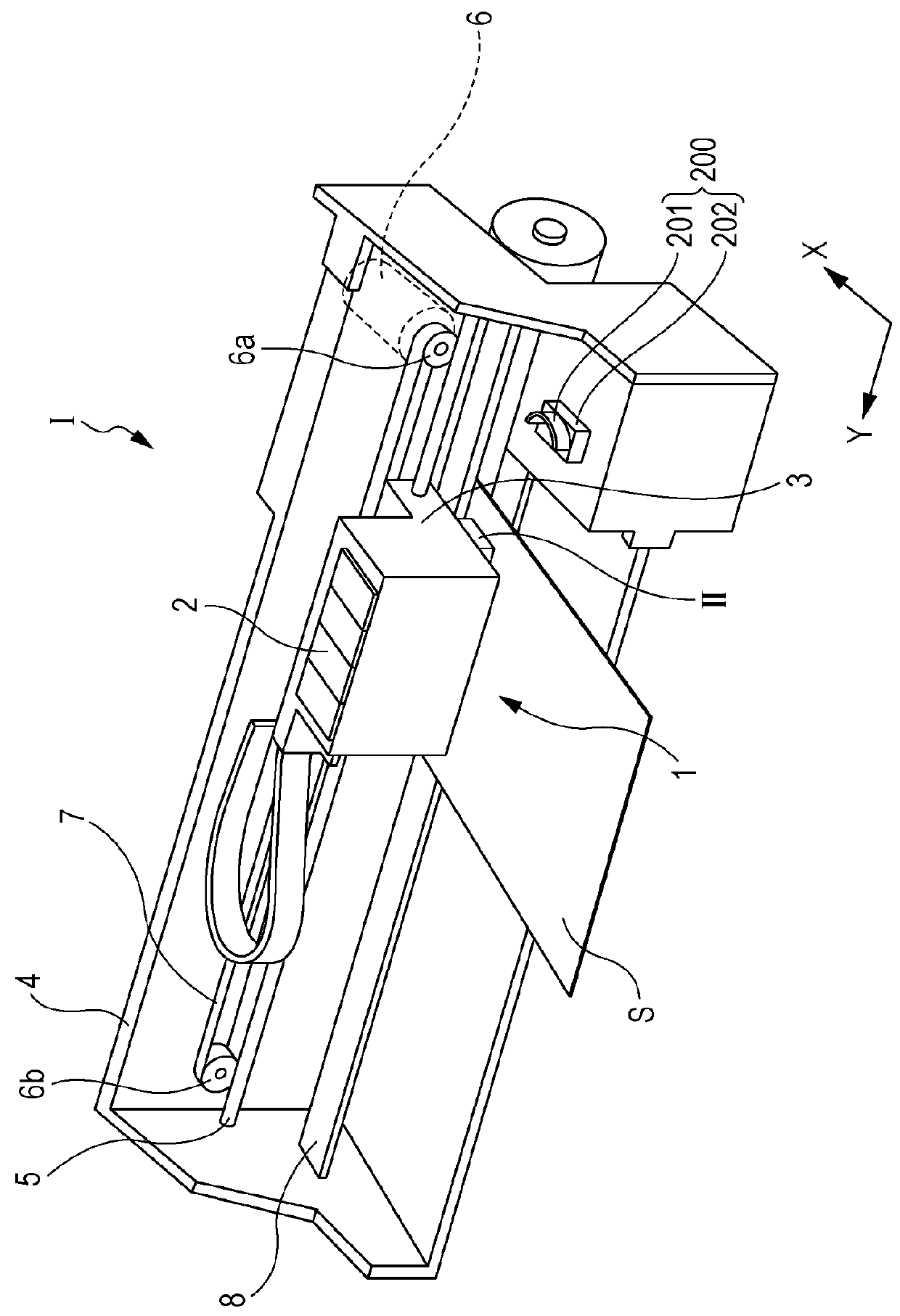
[0039]FIG. 1 is a perspective view that shows a schematic configuration of an ink jet type recording apparatus, which is an example of a liquid ejecting apparatus according to Embodiment 1 of the invention.

[0040]As shown in FIG. 1, an ink jet type recording apparatus I, which is a liquid ejecting apparatus of the present embodiment, is provided with an ink jet type recording head unit 1 (hereinafter, also referred to as a head unit 1) that has a plurality of ink jet type recording heads II (hereinafter, also referred to as recording heads II). Ink cartridges 2 that configure ink supply means are provided in the head unit 1 in a detachable manner, and a carriage 3 in which the head unit 1 is equipped is provided so as to be movable in an axial direction on a carriage axis 5 that is attached to an apparatus main body 4. The head unit 1 is set as a head unit that discharges a black ink composition and a color ink composition.

[0041]In addition, a driving motor 6 is provided in the vicin...

embodiment 2

[0103]FIG. 13 is a cross-sectional view in which a main section of an ink jet type recording head, which is an example of a liquid ejecting head according to Embodiment 2 of the invention has been enlarged. Additionally, the same reference numerals are applied to members which are the same as in the abovementioned Embodiment 1, and overlapping descriptions thereof have been omitted.

[0104]As shown in FIG. 13, the nozzle plate 20 of the present embodiment is provided to extend to a region of the communication plate 15 in which the compliance substrate 45 is joined.

[0105]Even with this kind of configuration, as long as a distance s8 of the first blank space section 23 is set to a total distance of the distance s1 and the interval s3 of the abovementioned Embodiment 1, the deformation of the blade section 201 is stabilized, and therefore, it is possible to suppress a circumstance in which the end nozzle opening 21 remains unwiped by the blade section 201. In addition, since the end sect...

embodiment 3

[0107]FIG. 14 is a cross-sectional view that shows the main sections of an ink jet type recording head, which is an example of a liquid ejecting head according to Embodiment 3 of the invention and the wiping section. Additionally, the same reference numerals are applied to members which are the same as in the abovementioned Embodiments, and overlapping descriptions thereof have been omitted.

[0108]As shown in FIG. 14, the blade section 201 of the wiping section 200 of the present embodiment has a convex portion 201a that protrudes toward the liquid ejecting surface 20a from the surface of the cover head 130.

[0109]Further, in addition to both sides of the convex portion 201a of the blade section 201 sweeping over the surface of the cover head 130, a leading end of the convex portion 201a sweeps over the liquid ejecting surface 20a.

[0110]Even with this kind of configuration, in the same manner as Embodiment 1 that is mentioned above, by making the distance s1 of the first blank space ...


PUM


Abstract

A liquid ejecting apparatus is provided with a liquid ejecting head that ejects a liquid from nozzle openings and a wiping section that sweeps over a liquid ejecting surface side of the liquid ejecting head, the liquid ejecting head is provided with a nozzle plate that has the liquid ejecting surface and a protective member which has an opening section, and which is provided to protrude further on a side of liquid discharge than the nozzle plate and which exposes the liquid ejecting surface, the wiping section sweeps over the liquid ejecting surface of the nozzle plate by moving toward a sweeping direction, which is an in-plane direction of the liquid ejecting surface, and, in the nozzle plate, a distance in an orthogonal direction, which is orthogonal to the sweeping direction, of a first blank space section from an end of the nozzle plate to an end nozzle opening that is provided on a side of the end is longer than a distance in the sweeping direction of a second blank space section from an end of the nozzle plate to an end nozzle opening that is provided on a side of the end.

Description

[0001]This application claims priority to Japanese Patent Application No. 2014-040876, filed Mar. 3, 2014, the entirety of which is incorporated by reference herein.BACKGROUND[0002]1. Technical Field[0003]The present invention relates to a liquid ejecting apparatus that is provided with a liquid ejecting head that ejects a liquid from a nozzle opening, and in particular, to an ink jet type recording apparatus that is provided with an ink jet type recording head that discharges ink as the liquid.[0004]2. Related Art[0005]Among liquid ejecting apparatuses that eject a liquid onto a target recording medium, for example, ink jet type recording apparatuses that perform printing on a target recording medium (ejection target medium) such as paper, a recording sheet or the like by ejecting ink as a liquid are known.[0006]Since the ink jet type recording heads with which these kind of ink jet type recording apparatuses are equipped discharge ink droplets onto the ejection target medium from ...

Claims


Application Information

Patent Timeline
Patent Type & Authority Patents(United States)
IPC IPC(8): B41J2/165B41J2/14
CPCB41J2/16535B41J2/1433B41J2/16538B41J2/14233B41J2002/14362B41J2002/14419B41J2002/14491
Inventor WATANABE, SHUNSUKE
Owner SEIKO EPSON CORP
Why Eureka
Try Eureka