
Rocket or artillery launched smart reconnaissance pod

a reconnaissance pod and rocket launch technology, applied in the field of reconnaissance, can solve the problems of high risk for forward observers and recon patrols, inability to achieve current or “up-to-date” status, and time-consuming, and achieve the effect of slowing down the rate of descen

Active Publication Date: 2016-01-12
LONESTAR INVENTIONS LP
View PDF30 Cites 23 Cited by
  • Summary
  • Abstract
  • Description
  • Claims
  • Application Information

AI Technical Summary

Benefits of technology

Enables accurate, real-time observation and data transmission over extended periods, reducing risk to personnel and resources, and simplifying data interpretation with commercially available devices, while requiring minimal additional training for deployment.

Problems solved by technology

This very valuable reconnaissance information contains massive amount of data which is related to a very large area, and it must be analyzed, which can be very time consuming.
As a result, the data gathering, processing and interpretation does not achieve current, or “up-to-date” status—on the order of minutes—after a request for reconnaissance is issued.
Needless to say forward observers and recon patrols are subject to very high risk and require planning ahead of time, which uses great amounts of valuable highly trained and skilled combat resources.
UAV's are becoming a very popular means of gathering visual data related to a specific area of interest, but they require dedicated skilled resources for piloting and data interpretation, and they cannot be deployed and activated instantaneously, and they cannot be at a desired location at a desired time reliably due to their launch constraints, limited range and nature of their flight characteristics, including speed and maneuverability.
Small, hand launched electrically powered UAV's have been developed, but their range and deployment duration are generally limited, measured in several miles and minutes, and since they have very limited speed, they may not timely arrive at a desired location.

Method used


Image

  • Rocket or artillery launched smart reconnaissance pod
  • Rocket or artillery launched smart reconnaissance pod
  • Rocket or artillery launched smart reconnaissance pod

Examples


Embodiment Construction

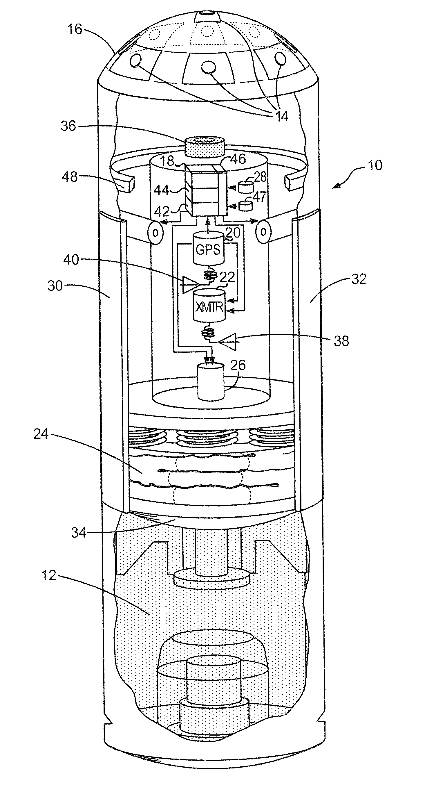
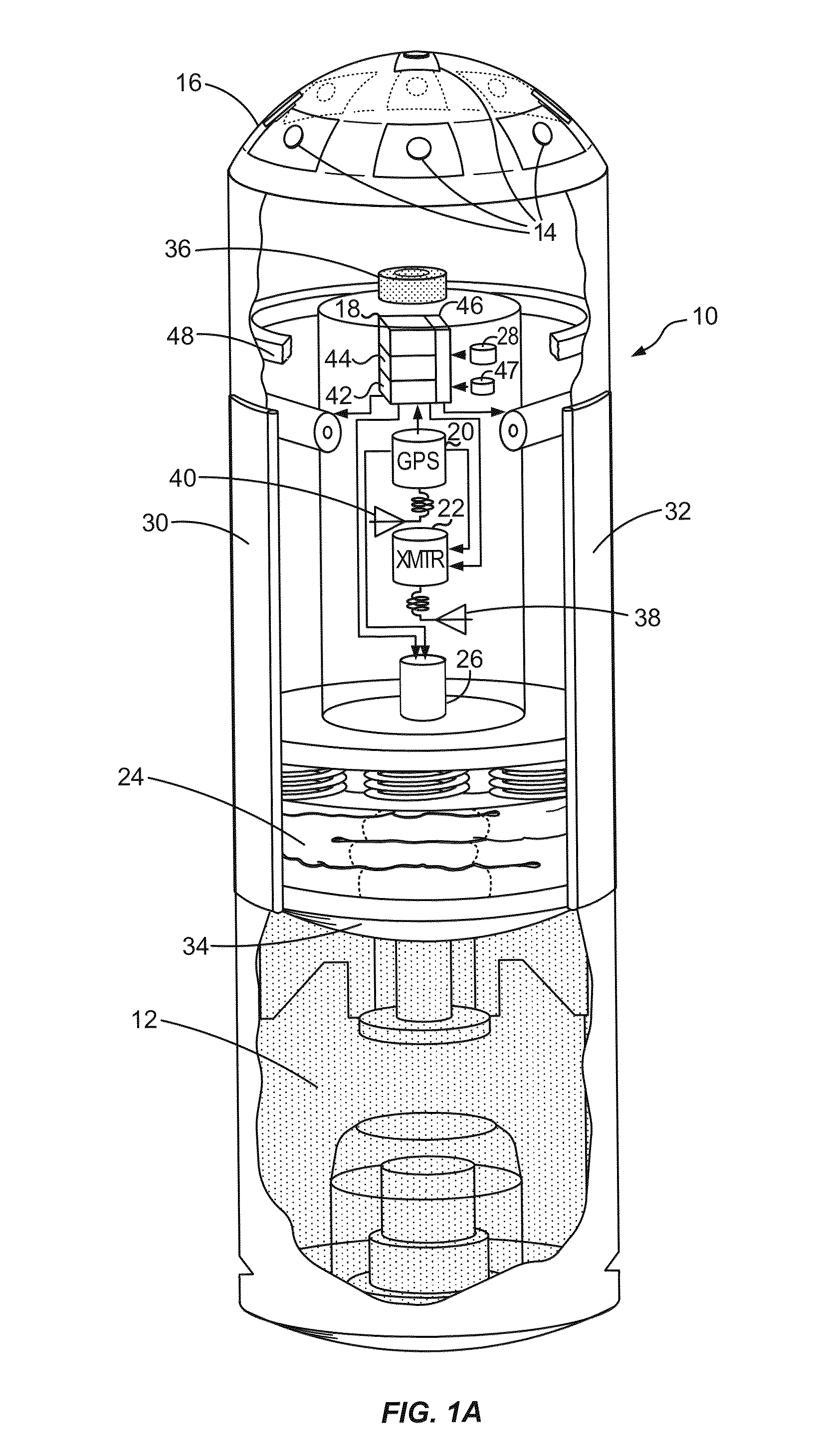
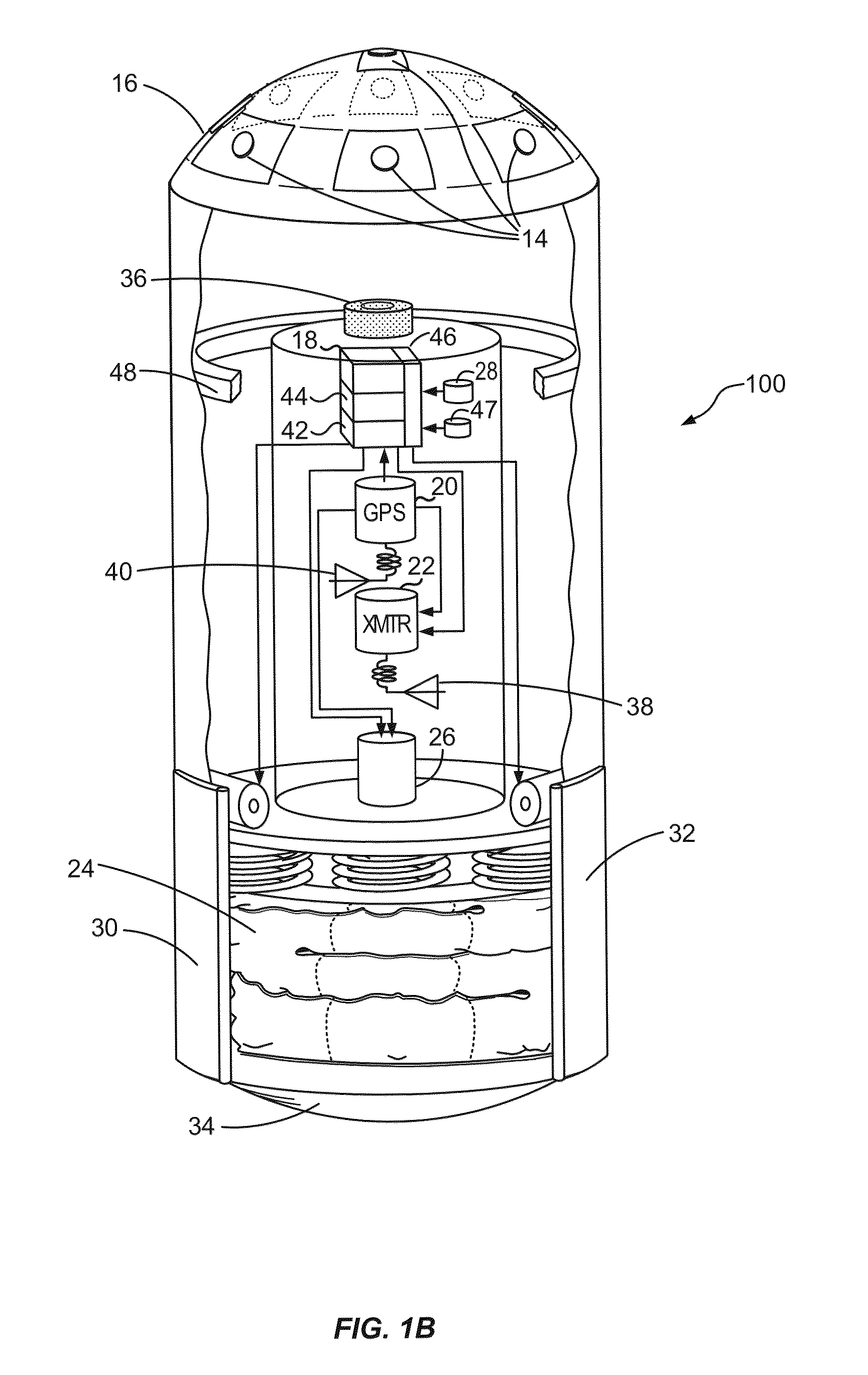
[0047]The invention in a specific embodiment includes a capsule or pod that matches the form factor, mass and mass distribution of a projectile (FIG. 1A, 1B) or has a form factor (FIG. 1B) that can be housed in a shell (FIG. 1C). The first embodiment (FIG. 1A) matches the form factor and mass of ordinance so that the ballistic characteristics closely match that of the projectile that it simulates, so that it can be launched from a variety of platforms. In the second embodiment, the form factor and weight is such that a plurality of pods can be installed as payload in place of explosive material so as to match the payload and weight distribution of an artillery shell. One example of a launcher for the first embodiment is an M203-type grenade launcher. In any embodiment, the pod is equipped with sensors and communication mechanisms so that it can communicate with a remote monitoring station that collects intelligence such as images and location.

[0048]For example, there are various typ...


PUM


Abstract

A modular reconnaissance capsule or reconnaissance pod is provided that is suitable for deployment by means of an artillery launching platform, such as a conventional 40 mm grenade launcher or 155 mm cannon wherein a parachute is deployed at a pre-calculated observation altitude, the parachute being designed to yield a sufficiently slow rate of descent to permit live video capture and transmission of images as forward observation information. Alternatively, pods according to the invention may also be air dropped from an aircraft, either piloted or pilotless, thus allowing the aircraft to operate at a safe distance and yet provide close reconnaissance even under a cloud cover. Accurate information about targeting dynamics is made available to the user through commercially available products. The invention complements other reconnaissance methods and provides easy-to-use real-time visual information for a desired area of interest.

Description

CROSS-REFERENCES TO RELATED APPLICATIONS[0001]NOT APPLICABLESTATEMENT AS TO RIGHTS TO INVENTIONS MADE UNDER FEDERALLY SPONSORED RESEARCH AND DEVELOPMENT[0002]NOT APPLICABLEREFERENCE TO A “SEQUENCE LISTING,” A TABLE, OR A COMPUTER PROGRAM LISTING APPENDIX SUBMITTED ON A COMPACT DISK[0003]NOT APPLICABLEBACKGROUND OF THE INVENTION[0004]The invention relates to reconnaissance, namely the gathering of up-to-date visual information related to a desired area of interest. More particularly, the invention is a launchable pod and method of using a launchable pod containing cameras, infrared sensors, GPS, magnetic compass and a radio transmitter which is deployed by ballistic means, such as rocket, grenade launcher, an artillery piece or an aircraft.[0005]There is an important void in the reconnaissance puzzle at a tactical level. That void is the need to observe a target without putting individuals and / or expensive or renewable observation vehicles at risk. “Current and instantaneous” visual ...

Claims


Application Information

Patent Timeline
Patent Type & Authority Patents(United States)
IPC IPC(8): F42B12/36B64D17/00F42B10/56F42B10/50F42B5/02F42B30/00F42B12/58
CPCF42B12/365B64D17/00F42B10/56F42B5/025F42B10/50F42B12/58F42B30/006
Inventor AKCASU, OSMAN ERSEDUSLU, IBRAHIM ONURLEBLEBICI, YUSUF
Owner LONESTAR INVENTIONS LP
Learn More