Electric connector including connector terminal with buffer portion

a technology of connector terminals and connectors, applied in the direction of coupling bases/cases, coupling device connections, electrical devices, etc., can solve the problems of /b>/i>b/i> being difficult to be bent, and achieve the effect of facilitating the bending

Inactive Publication Date: 2015-12-22
DAIICHI SEIKO CO LTD
View PDF40 Cites 18 Cited by
  • Summary
  • Abstract
  • Description
  • Claims
  • Application Information

AI Technical Summary

Benefits of technology

[0018]In the connector terminal in accordance with the present invention, the buffer portion is smaller in width or thickness than the first and second contacts. Thus, even if the buffer portion were hammered in order to design the buffer portion to be smaller in width or thickness than the first and second contacts, the buffer portion would be hammered only in width-wise or thickness-wise direction thereof, and hence, it would be possible to avoid the buffer portion from being too hard, and further, it would be possible for the buffer portion to be more bendable than the first and second contacts, keeping rigidity of the first and second contacts as it is. Thus, the buffer portion can absorb any positional gap between the first and second objects, even though the positional gap is slight.
[0020]The buffer portion designed to be curved in a width-wise direction would be readily bent when the opposite ends of the connector terminal are deflected in a thickness-wise direction, because the buffer portion is thin in a thickness-wise direction, and could be bent in a width-wise direction when the opposite ends of the connector terminal are deflected in a width-wise direction, because a degree of curvature of the buffer portion is made higher at one side and lower at the other side. The buffer portion designed to be curved in a thickness-wise direction would be difficult to be bent when the opposite ends of the connector terminal are deflected in a width-wise direction, but would be readily bent in a thickness-wise direction, because the buffer portion is thin in a thickness-wise direction, and further because a degree of curvature is made higher at one side and lower at the other side.
[0025]By folding a plate into two layers to design the first and second contacts to be thicker than the buffer portion, the buffer portion can be prevented from being hardened by being pressed.
[0027]By forming the first and second contacts and buffer portion in the above-mentioned manner, the connector terminal including the first and second contacts both of which are relatively thick, and the buffer portion which is relatively thin can be readily fabricated.
[0033]It is possible to arrange the guides without a space, ensuring that the connector terminals can be arranged at a small pitch.
[0035]In the connector terminal in accordance with the present invention, since the buffer portion is designed to be thinner in a width-wise or thickness-wise direction than the first and second contacts, the buffer portion can be bent more readily than the first and second contacts when the connector terminal is inserted into a housing, ensuring the buffer portion can absorb the deflection between opposite ends thereof.

Problems solved by technology

However, if the portion 73b is hammered to thereby have a smaller diameter, a metal density and hence a hardness of the portion 73b increases by being hammered, resulting in that the portion 73b is difficult to be bent.

Method used


Image

  • Electric connector including connector terminal with buffer portion
  • Electric connector including connector terminal with buffer portion
  • Electric connector including connector terminal with buffer portion

Examples


first embodiment

[0077]The electric connector in accordance with the first embodiment of the present invention will be explained hereinbelow with reference to the drawings.

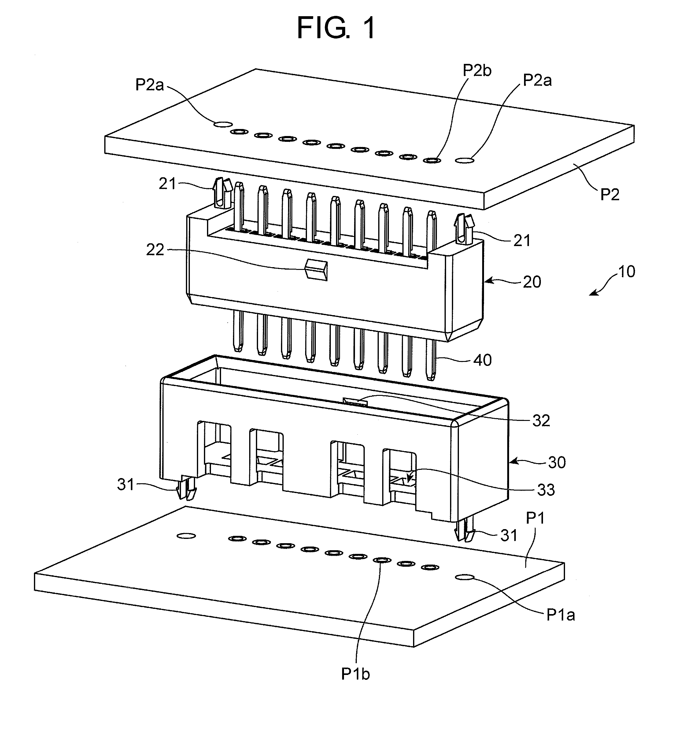
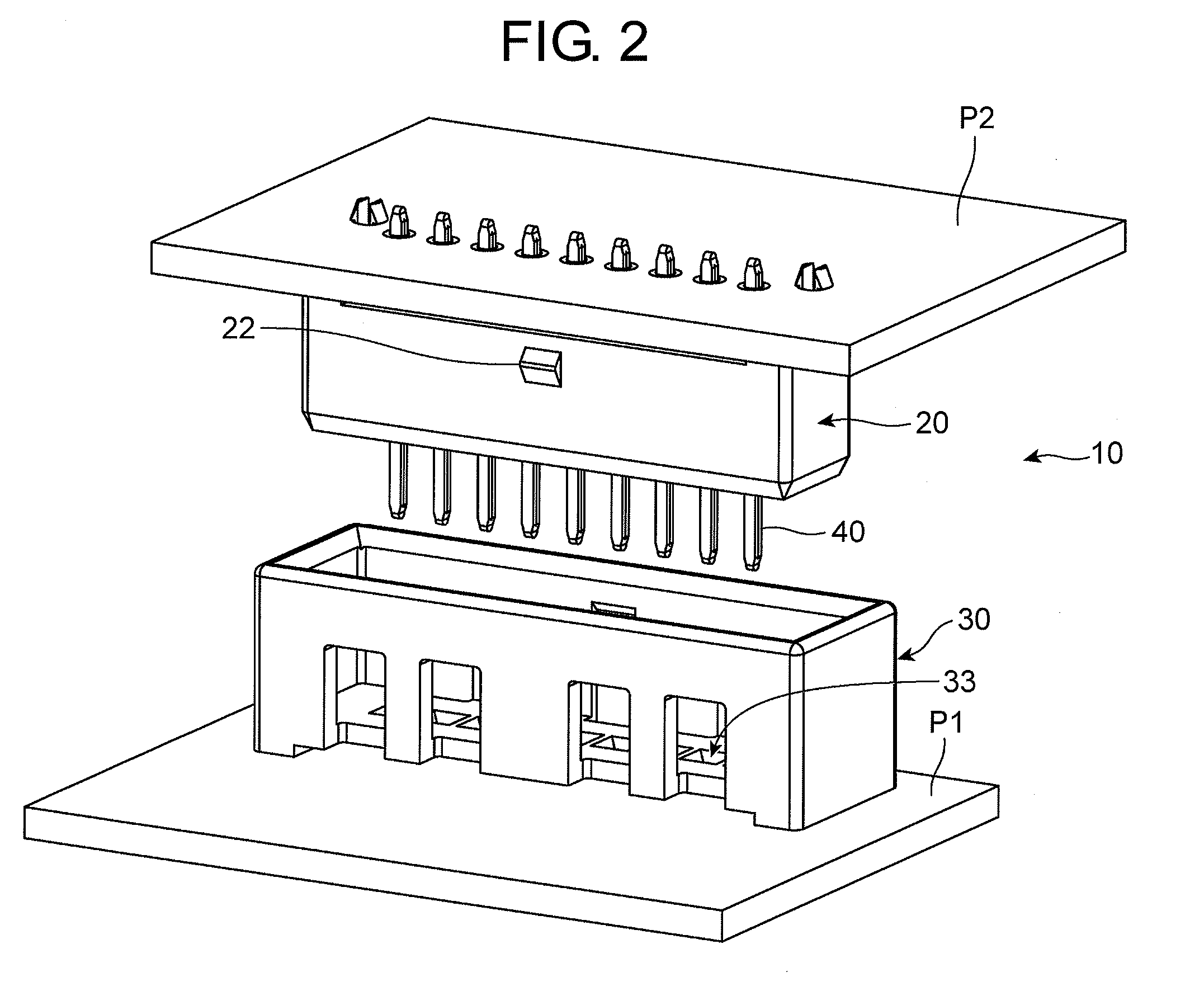
[0078]As illustrated in FIGS. 1 and 2, the electric connector 10 in accordance with the first embodiment may be used to electrically connect printed circuit boards equipped in an automobile to each other, for instance. The electric connector 10 electrically connects a printed circuit board P1 as an example of a first object to a printed circuit board P2 as an example of a second object.

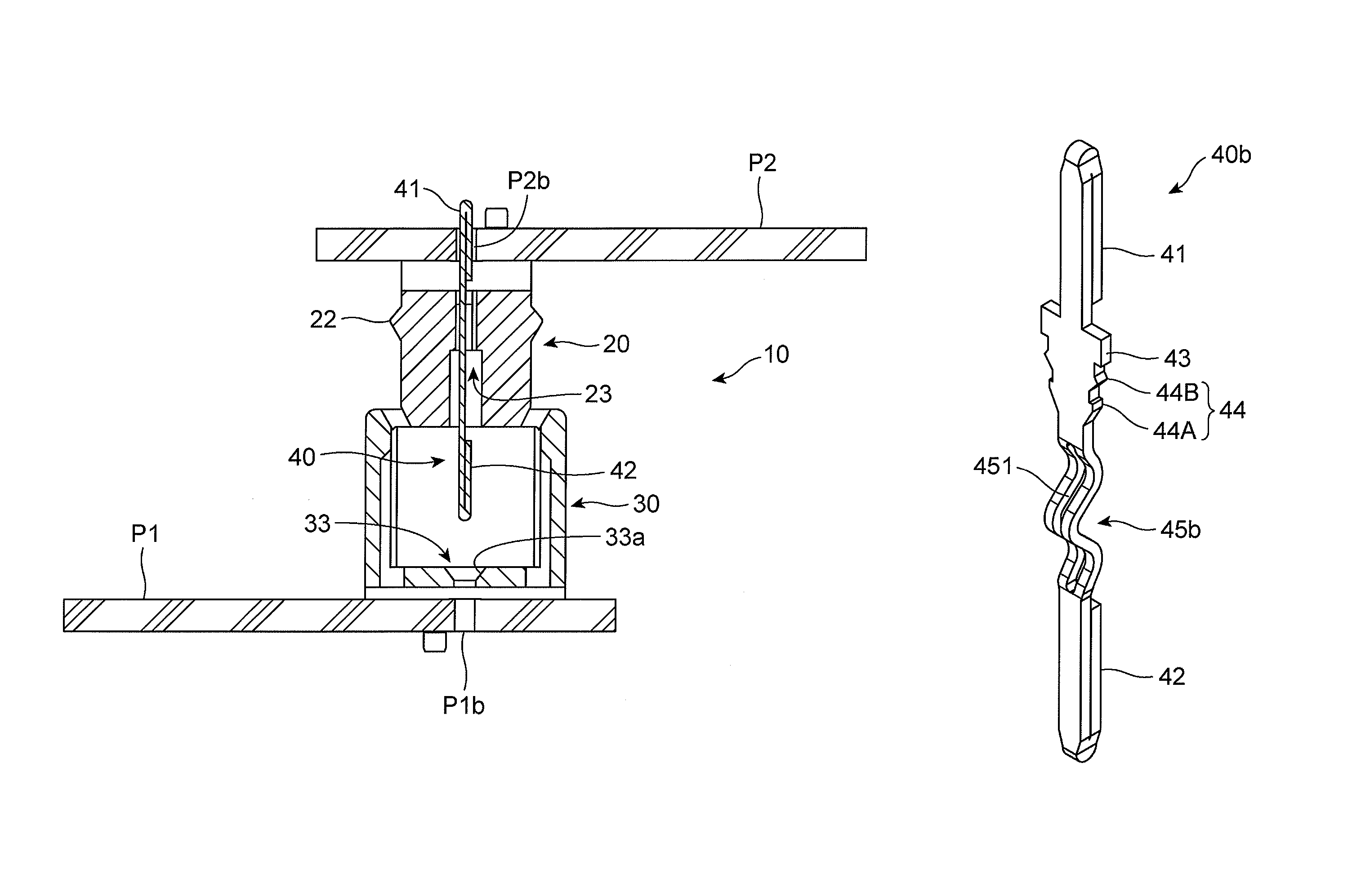
[0079]The electric connector 10 includes a male housing 20 mounted on the printed circuit board P2, a female housing 30 mounted on the printed circuit board P1 and fit to the male housing 20, a plurality of connector terminals 40 arranged in a line in the male housing 20.

[0080]The male housing 20 is designed to be almost a rectangular parallelepiped. The male housing 20 is formed at opposite ends at a bottom with a pair of bosses 21 inserted into th...

second embodiment

[0100]The electric connector in accordance with the second embodiment of the present invention is explained hereinbelow with reference to the drawings. The female housing 30x in the electric connector 10x in accordance with the second embodiment is designed to include a plurality of female connector terminals into which the connector terminals 40 are inserted. In FIGS. 13 to 15, parts or elements that correspond to those of the electric connector illustrated in FIG. 1 have been provided with the same reference numerals, and will not be explained.

[0101]The electric connector 10x in accordance with the second embodiment, illustrated in FIGS. 13 and 14, includes a male housing 20x mounted on a printed circuit board (not illustrated) as a first object, a plurality of connector terminals 40 housed in the male housing 20x, a female housing 30x mounted on the printed circuit board P2 as a second object, and a plurality of female connector terminals 50 housed in the female housing 30x.

[010...


PUM


Abstract

A connector terminal includes a first contact at one end, a second contact at the other end, and a buffer portion, the connector terminal electrically connecting a first object connected to the first contact to a second object connected to the second object, the buffer portion being bent in accordance with a positional gap between the first and second objects, the buffer portion having a cross-sectional area smaller than the same of the first and second contacts.

Description

BACKGROUND OF THE INVENTION[0001]1. Field of the Invention[0002]The invention relates to a connector terminal for electrically connecting objects such as printed circuit boards to each other, and further to an electric connector including the connector terminal.[0003]2. Description of the Related Art[0004]There is known an electric connector including a plurality of needle-shaped connector terminals each having contact at opposite ends thereof, a male housing in which the connector terminals are arranged in a line and which is mounted on a first printed circuit board, and a female housing into which the male housing is fit and which is mounted on a second printed circuit board. The connector terminal at the contact formed at one end thereof passes a through-hole formed through the female housing, and is inserted into a through-hole formed through the second printed circuit board, thereby the first and second printed circuit boards are electrically connected to each other.[0005]In an...

Claims


Application Information

Patent Timeline
Patent Type & Authority Patents(United States)
IPC IPC(8): H01R12/00H01R13/46H01R12/73H01R12/91
CPCH01R13/46H01R12/91H01R12/73
Inventor ENDO, TAKAYOSHIYAGI, SAKAIMUTA, MASAYAOOHASHI, SHUNYA
Owner DAIICHI SEIKO CO LTD
Why Eureka
Try Eureka