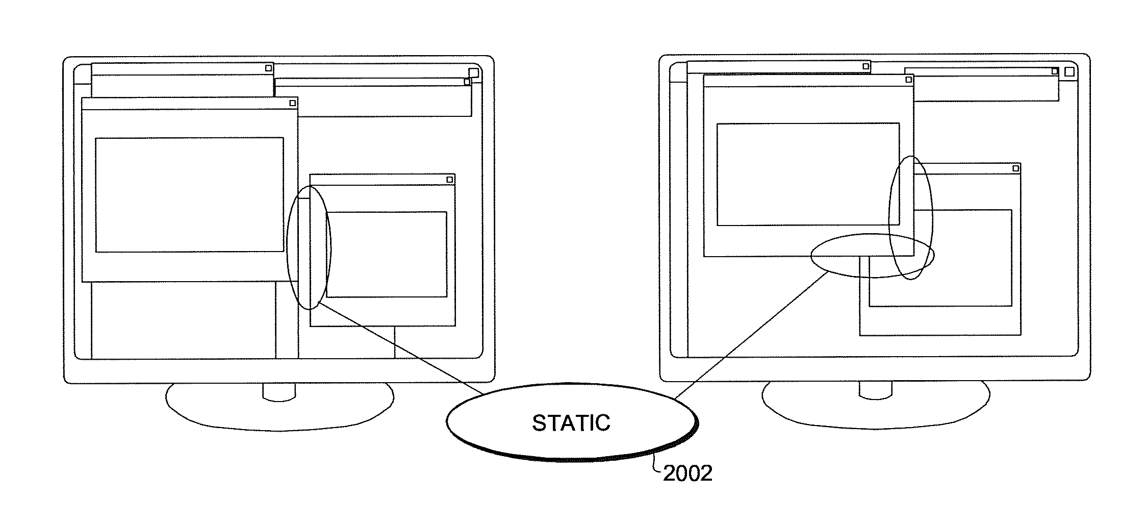
Video window detection
a technology for video window detection and detection detection, applied in the field of video window detection, can solve problems such as over enhancement or addition of image artifacts
- Summary
- Abstract
- Description
- Claims
- Application Information
AI Technical Summary
Benefits of technology
Problems solved by technology
Method used
Image

Examples
Embodiment Construction
[0130]The following describes in further detail suitable apparatus and possible mechanisms for the provision of video decoding.
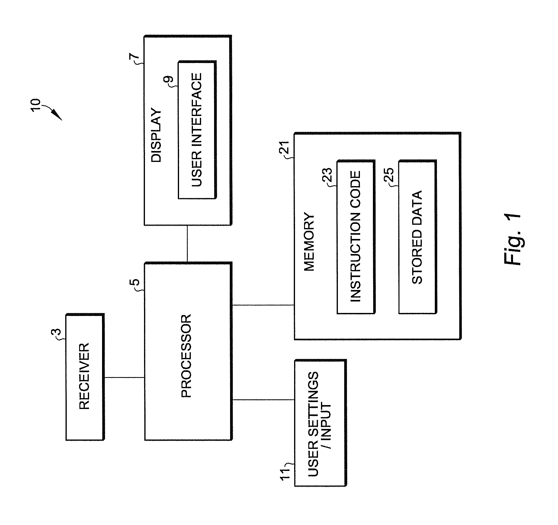
[0131]With respect to FIG. 1 an example system employing an electronic device or apparatus 10 is shown within which embodiments of the application can be implemented.
[0132]The apparatus 10 in some embodiments comprises a receiver 3 configured to receive a PC RGB (Red-Green-Blue) signal through a digital cable. The cable can for example be a DVI (Digital Video Interface), HDMI (High Definition Multimedia Interface), or a DP (DisplayPort) cable. However any suitable cable and video encoding format can be used to receive the signal. In some embodiments the receiver 3 can be controlled by the processor 5 to select the channel to be received.
[0133]The apparatus 10 in some embodiments comprises a processor 5 which can be configured to execute various program codes. The implemented program codes can comprise a LCD monitor / TV controller / Display controller for receiv...
PUM
 Abstract
Description
Claims
Application Information
 - R&D
- Intellectual Property
- Life Sciences
- Materials
- Tech Scout
- Unparalleled Data Quality
- Higher Quality Content
- 60% Fewer Hallucinations
Browse by: Latest US Patents, China's latest patents, Technical Efficacy Thesaurus, Application Domain, Technology Topic, Popular Technical Reports.
© 2025 PatSnap. All rights reserved.Legal|Privacy policy|Modern Slavery Act Transparency Statement|Sitemap|About US| Contact US: help@patsnap.com