
Method and/or apparatus for implementing high dynamic range image processing in a video processing system

a video processing system and high dynamic range technology, applied in the field of image processing, can solve the problems of lack of detail in the shadow and/or highlight regions of natural scenes in conventional camera images

Active Publication Date: 2015-12-01
AMBARELLA INT LP
View PDF12 Cites 22 Cited by
  • Summary
  • Abstract
  • Description
  • Claims
  • Application Information

AI Technical Summary

Benefits of technology

The present invention is an image processing system that can apply high dynamic range (HDR) processing to videos. It can do so at the CFA level and provide an economical way to implement HDR processing.

Problems solved by technology

Conventional camera images often lack detail in the shadow and / or highlight regions present in natural scenes compared with similar scenes directly perceived by the human eye.

Method used


Image

  • Method and/or apparatus for implementing high dynamic range image processing in a video processing system
  • Method and/or apparatus for implementing high dynamic range image processing in a video processing system
  • Method and/or apparatus for implementing high dynamic range image processing in a video processing system

Examples


Embodiment Construction

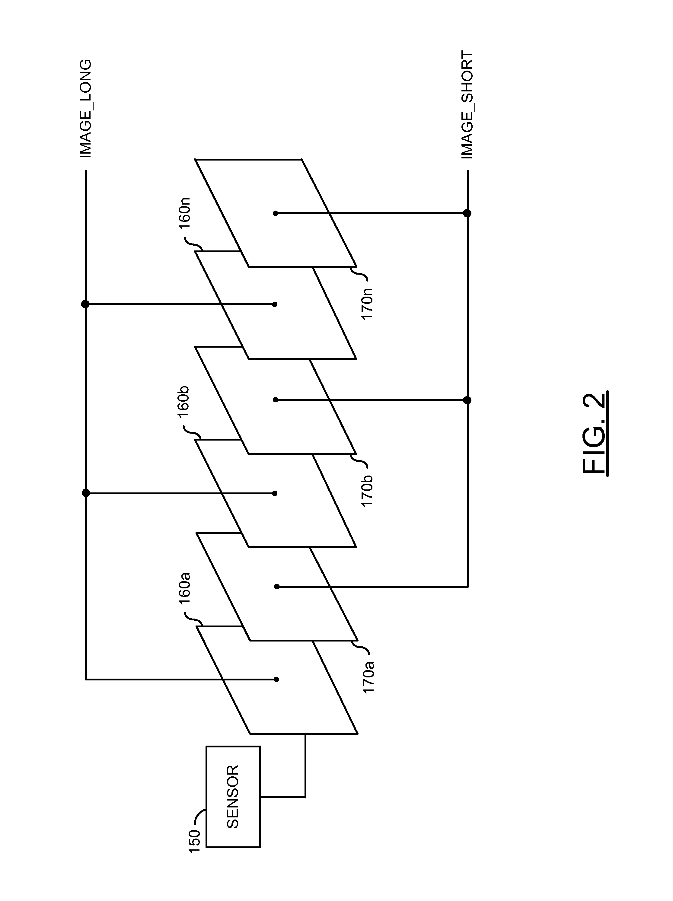
[0014]Referring to FIG. 1, a block diagram of a system 100 is shown in accordance with a preferred embodiment of the present invention. In one example, the system 100 may be implemented as an integrated circuit (IC). In another example, the system 100 may be implemented as more than one integrated circuit. The circuit 100 may be used to implement high dynamic range (HDR) image fusion processing in a video environment.

[0015]The system 100 generally comprises a block (or circuit) 102, a block (or circuit) 104, a block (or circuit) 106, and a block (or circuit) 108. The circuit 102 may be implemented as a scaling circuit. The circuit 104 may be implemented as an alpha blending circuit. The circuit 106 may be implemented as an average neighborhood luma circuit. The circuit 108 may be implemented as a demosaic circuit.

[0016]The circuit 102 may have an input 110 that may receive a signal (e.g., IMAGE_LONG) and an output 112 that may present a signal (e.g., IMAGE_LONG_SCALED). The circuit ...


PUM


Abstract

An apparatus comprising a scaling circuit, a luma circuit and a blending circuit. The scaling circuit may generate a plurality of scaled frames in response to a first plurality of frames generated by a sensor. The first plurality of frames may have a first exposure. The luma circuit may generate an average luminance value for each of a plurality of processed pixels in each of a second of the plurality of frames generated by the sensor. The second of the plurality of frames may have a second exposure and each of the average luminance values is calculated based on a plurality of neighboring pixels in a neighborhood of the processed pixel.

Description

FIELD OF THE INVENTION[0001]The present invention relates to image processing generally and, more particularly, to a method and / or apparatus for implementing high dynamic range image processing in a video processing system.BACKGROUND OF THE INVENTION[0002]Dynamic range is the ratio between the maximum and minimum values of a physical measurement. The dynamic range of real-world scenes can be quite high (i.e., ratios of 100,000:1 are common in the natural world). The human eye is able to perceive such high dynamic ranges in real-world scenes. Dynamic range in an image processing system is considered the ratio between the brightest and darkest parts of a particular scene or picture. For a camera sensor environment, dynamic range is defined as the ratio between the largest possible measurement and the smallest possible measurement the sensor can generate. The largest measurement is limited by the physical pixel well size. The smallest measurement is limited by the physical noise floor....

Claims


Application Information

Patent Timeline
IPC IPC(8): H04N7/12H04N19/44H04N7/52H04N11/02H04N5/235H04N5/355H04N19/98
CPCH04N7/52H04N7/12H04N5/355H04N19/98H04N5/2355H04N23/741H04N23/73H04N25/57H04N9/74
Inventor KWOK, WILSONKOHN, LESLIE D.
Owner AMBARELLA INT LP
Learn More