Power regenerative converter and power conversion apparatus

a technology of power regenerative converter and power conversion apparatus, which is applied in the direction of electric generator control, dynamo-electric converter control, dynamo-electric gear control, etc., can solve problems such as resonance phenomena

Active Publication Date: 2015-11-17
YASKAWA DENKI KK
View PDF12 Cites 5 Cited by
  • Summary
  • Abstract
  • Description
  • Claims
  • Application Information

AI Technical Summary

Benefits of technology

[0007]Such a filter includes a reactor and a capacitor. Hence, the filter becomes a cause of the occurrence of a resonance phenomenon. With respect to this, for example, in a power regenerative converter described in JP-A-2006-340466, a damping resistor is added to an LCL filter to suppress the resonance phenomenon.

Problems solved by technology

Hence, the filter becomes a cause of the occurrence of a resonance phenomenon.

Method used


Image

  • Power regenerative converter and power conversion apparatus
  • Power regenerative converter and power conversion apparatus
  • Power regenerative converter and power conversion apparatus

Examples


first embodiment

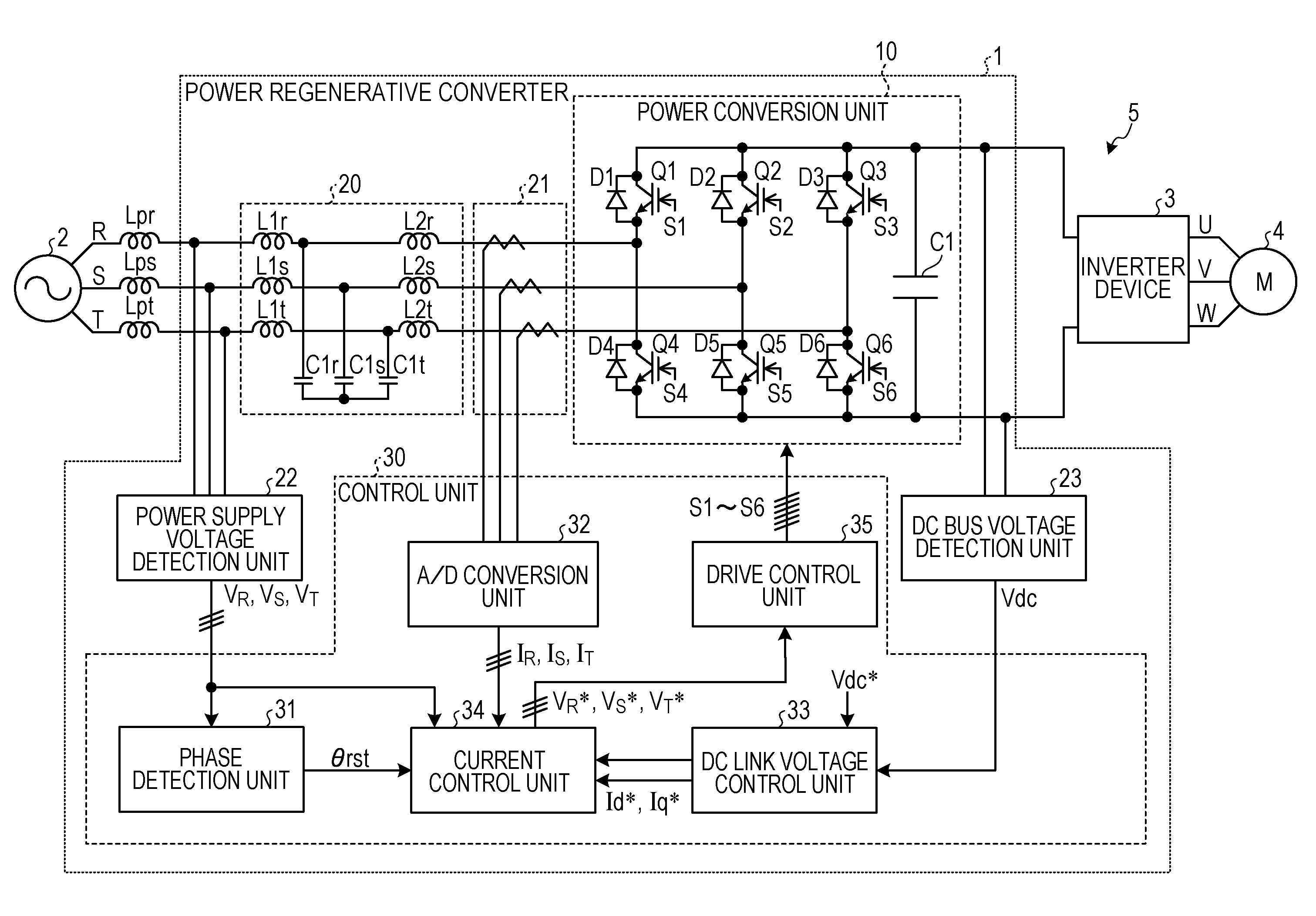
[0019]FIG. 1 is a diagram illustrating an exemplary configuration of a power regenerative converter according to a first embodiment. As illustrated in FIG. 1, a power regenerative converter 1 according to the first embodiment is arranged between a three-phase AC power supply 2 and an inverter device 3. The power regenerative converter 1 converts power between the three-phase AC power supply 2 and the inverter device 3. The power regenerative converter 1 can convert AC power into DC power and convert DC power into AC power. In other words, the power regenerative converter 1 can perform bidirectional power conversion.

[0020]A power conversion apparatus 5 includes the power regenerative converter 1 and the inverter device 3. The operation state of the power conversion apparatus 5 is switched between a motoring operation state that drives a motor 4, and a regenerative operation state that generates regenerative electric power to the three-phase AC power supply 2.

[0021]Upon motoring opera...

second embodiment

[0105]Next, a description will be given of a power regenerative converter according to a second embodiment. In the power regenerative converter 1 according to the first embodiment, the capacitor voltage Vc is estimated. On the other hand, a power regenerative converter 1A according to the second embodiment includes a capacitor voltage detecting unit 71 that detects the capacitor voltage Vc. In the second embodiment, the same reference numerals are assigned to components having the same functions as the components indicated in the first embodiment. Their descriptions will be omitted. Moreover, for convenience of description, a part of the configuration is not illustrated.

[0106]FIG. 8 is a diagram illustrating an exemplary configuration of the power regenerative converter 1A according to the second embodiment. As illustrated in FIG. 8, the power regenerative converter 1A includes the capacitor voltage detecting unit 71 and a control unit 30A.

[0107]The capacitor voltage detecting unit ...


PUM


Abstract

A power regenerative converter includes: a power conversion unit configured to convert AC power supplied from an AC power supply into DC power and convert DC power into AC power to be supplied as regenerative electric power to the AC power supply; an LCL filter including a reactor unit having a plurality of reactors connected in series between the power conversion unit and the AC power supply, and capacitors each having one end connected to a series connection point of the reactors in the reactor unit; a drive control unit for controlling the power conversion unit based on an AC voltage command; and a voltage command compensation unit for calculating a compensation value in accordance with a capacitor voltage being a voltage at the series connection point of the reactors and adding the compensation value to the AC voltage command input to the drive control unit.

Description

CROSS-REFERENCE TO RELATED APPLICATION[0001]The present application claims priority under 35 U.S.C. §119 to Japanese Patent Application No. 2012-097133, filed Apr. 20, 2012. The contents of this application are incorporated herein by reference in their entirety.BACKGROUND[0002]1. Technical Field[0003]The embodiments disclosed herein relate to a power regenerative converter and a power conversion apparatus.[0004]2. Related Art[0005]A power regenerative converter is conventionally known as a power regeneration apparatus. A power regenerative converter is arranged, for example, between an inverter device for controlling a motor and a three-phase AC power supply. Upon deceleration of the motor, electric power is supplied from the motor to the power regenerative converter through the inverter device. The power regenerative converter converts the power into AC power by switching elements, and supplies the AC power to the three-phase AC power supply.[0006]Known as conduction modes of the p...

Claims


Application Information

Patent Timeline
Patent Type & Authority Patents(United States)
IPC IPC(8): H02M5/458H02M7/797H02P9/04H02P21/00H02M7/68H02M5/44H02M7/219H02M1/16
CPCH02M7/68H02M5/44H02M7/219H02M7/797H02P9/04H02P21/0096H02M1/16H02M5/4585H02P21/50
Inventor TAKASE, YOSHIYASUIDE, KOZOMORIMOTO, SHINYAIURA, HIDEAKISAEKI, TAKAHIRO
Owner YASKAWA DENKI KK
Why Eureka
Try Eureka