
Method and apparatus for inverter output current harmonic reduction

a technology of output current and harmonic reduction, which is applied in the field of power conversion, can solve the problems of undesirable harmonics in the generated output current, undesirable increase in size and cost of the inverter, etc., and achieve the effect of reducing harmonic distortion

Active Publication Date: 2015-11-10
ENPHASE ENERGY
View PDF21 Cites 5 Cited by
  • Summary
  • Abstract
  • Description
  • Claims
  • Application Information

AI Technical Summary

Benefits of technology

This approach effectively reduces harmonic distortion in power conversion modules, achieving compliance with regulatory standards while minimizing size and cost by using active harmonic compensation, thereby enhancing the efficiency and cost-effectiveness of power conversion systems.

Problems solved by technology

During the power conversion process, non-ideal circuit behavior may result in undesirable harmonics in the generated output current.
Due to the relatively low frequencies of some harmonic components, the components required for the passive filters would be bulky and expensive, leading to an undesirable increase in size and cost of the inverter.

Method used


Image

  • Method and apparatus for inverter output current harmonic reduction
  • Method and apparatus for inverter output current harmonic reduction
  • Method and apparatus for inverter output current harmonic reduction

Examples


Embodiment Construction

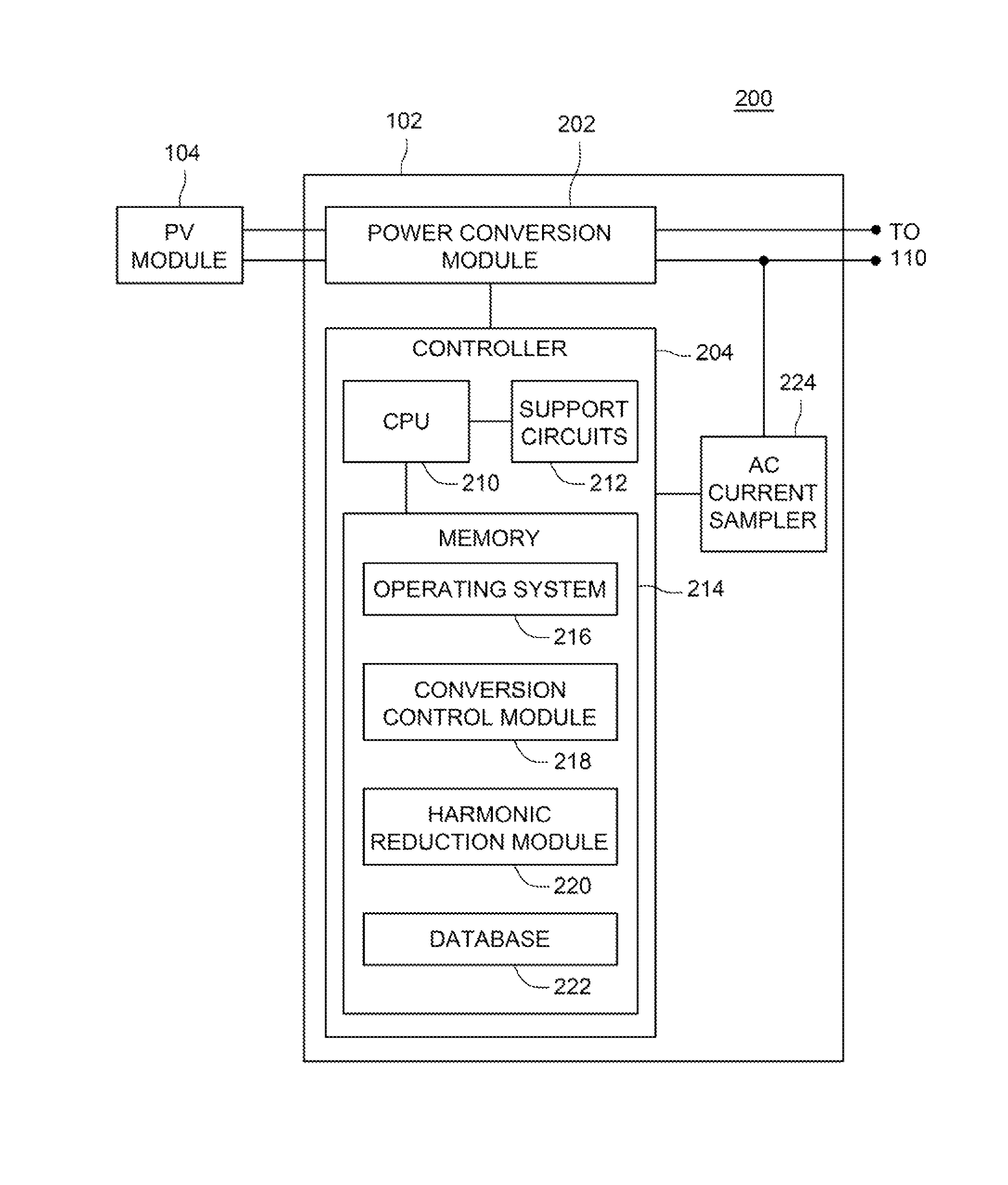
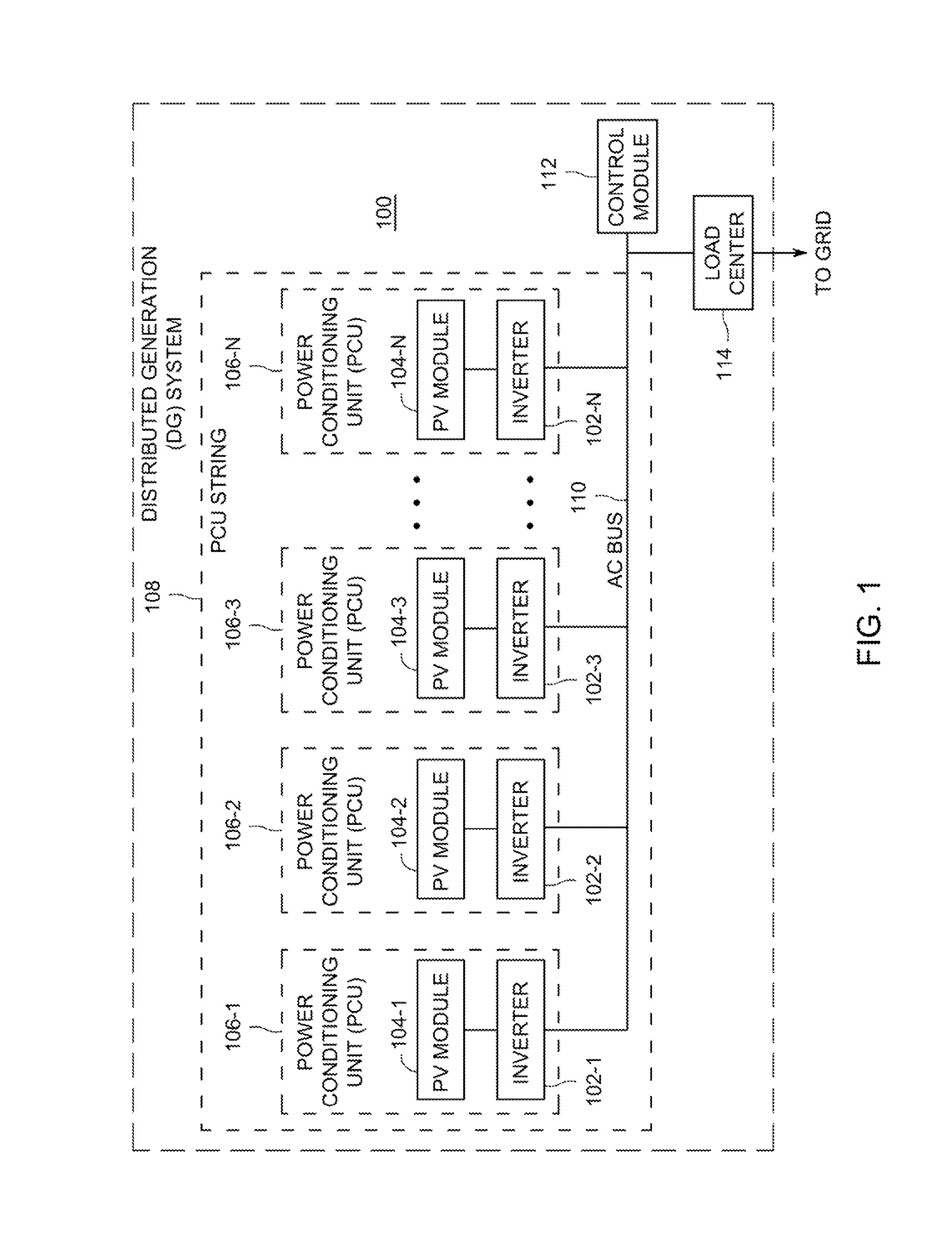
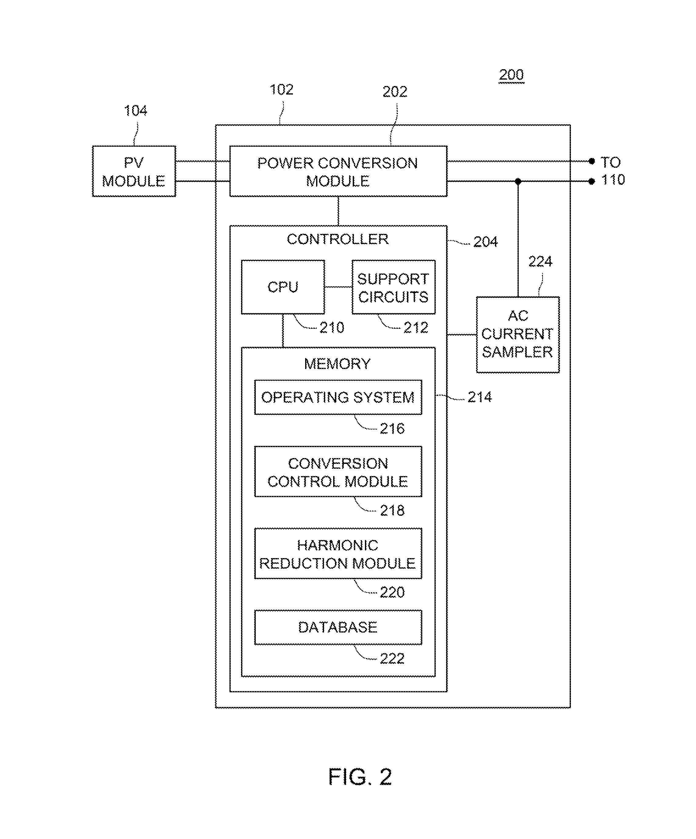
[0015]FIG. 1 is a block diagram of a distributed generator (DG) system 100 in accordance with one or more embodiments of the present invention. This diagram only portrays one variation of the myriad of possible system configurations. The present invention can function in a variety of distributed power generation environments and systems.

[0016]The DG system 100 (“system 100”) comprises a plurality of inverters 102-1, 102-2 . . . 102-n, collectively referred to as inverters 102 (or power conversion modules 102), a plurality of PV modules 104-1, 104-2 . . . 104-n, collectively referred to as PV modules 104, an AC bus 110, and a load center 114.

[0017]Each inverter 102-1, 102-2, 102-3, . . . 102-n is coupled to a PV module 104-1, 104-2, 104-3, . . . 104-n, respectively, in a one-to-one correspondence. In some embodiments, a DC-DC converter may be coupled between each PV module 104 and each inverter 102 (e.g., one DC-DC converter per PV module 104). Alternatively, multiple PV modules 104 ...


PUM


Abstract

Method and apparatus for reducing harmonic distortion. In one embodiment, the method comprises determining an inverter output current waveform; determining a plurality of harmonic components of the inverter output current waveform; determining, based on the plurality of harmonic components, a plurality of harmonic compensation components; and generating a compensating current comprising the plurality of harmonic compensation components.

Description

CROSS-REFERENCE TO RELATED APPLICATIONS[0001]This application claims benefit of U.S. provisional patent application Ser. No. 61 / 694,022, filed Aug. 28, 2012, which is herein incorporated in its entirety by reference.BACKGROUND OF THE INVENTION[0002]1. Field of the Invention[0003]Embodiments of the present disclosure relate generally to power conversion and, in particular, to reducing harmonics in output current from a power conversion module.[0004]2. Description of the Related Art[0005]Solar panels, or photovoltaic (PV) modules, convert energy from sunlight received into direct current (DC). The PV modules cannot store the electrical energy they produce, so the energy must either be dispersed to an energy storage system, such as a battery or pumped hydroelectricity storage, or dispersed by a load. One option to use the energy produced is to employ one or more inverters to convert the DC current into an alternating current (AC) and couple the AC current to the commercial power grid. ...

Claims


Application Information

Patent Timeline
Patent Type & Authority Patents(United States)
IPC IPC(8): H02M1/12H02M7/04H02M1/00H02J3/38
CPCH02M1/12H02M7/04H02J3/383H02M2001/0009Y02E10/563H02J2300/24H02J3/381Y02E10/56H02J3/40H02M1/0009
Inventor ACKER, BRIANBARNES, ANDREW
Owner ENPHASE ENERGY
Learn More