
Steered-electron electric-field (SEEF) sensor program

a technology of electric field and sensor program, applied in the direction of magnetic measurement, electric discharge tube, instruments, etc., can solve the problem of low frequency insensitivity, and achieve the effect of improving the electric field sensor and manufacturing method, and increasing the sensitivity to electric fields

Inactive Publication Date: 2015-11-10
PALO ALTO RES CENT INC
View PDF3 Cites 10 Cited by
  • Summary
  • Abstract
  • Description
  • Claims
  • Application Information

AI Technical Summary

Benefits of technology

The invention provides an improved electric-field sensor that is smaller and more sensitive than previous sensors. It can detect low-power electric fields without needing physical contact. This allows for long-term monitoring of electric fields for various applications, such as person detection and underground facility monitoring. The sensors can accurately measure and characterize electromagnetic field data over a wide range of frequencies.

Problems solved by technology

Although such systems may be more compact than antenna systems, they are insensitive at low frequencies (e.g., frequencies below 100 MHz).

Method used


Image

  • Steered-electron electric-field (SEEF) sensor program
  • Steered-electron electric-field (SEEF) sensor program
  • Steered-electron electric-field (SEEF) sensor program

Examples


Embodiment Construction

[0023]Various embodiments and aspects of the invention will be described with reference to details discussed below, and the accompanying drawings will illustrate the various embodiments. The following description and the drawings are illustrative of the invention and are not to be construed as limiting the invention. Numerous specific details are described to provide a thorough understanding of various embodiments of the present invention. However, in certain instances, well-known or conventional details are not described in order to provide a concise discussion of embodiments of the present inventions. All terms used herein are intended to have their ordinary meaning in the art unless otherwise provided.

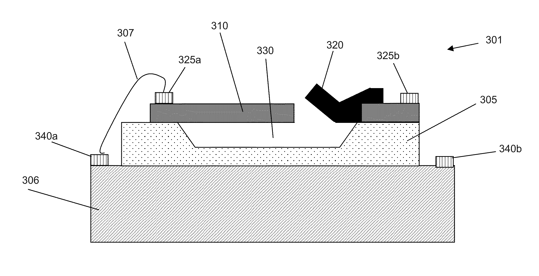
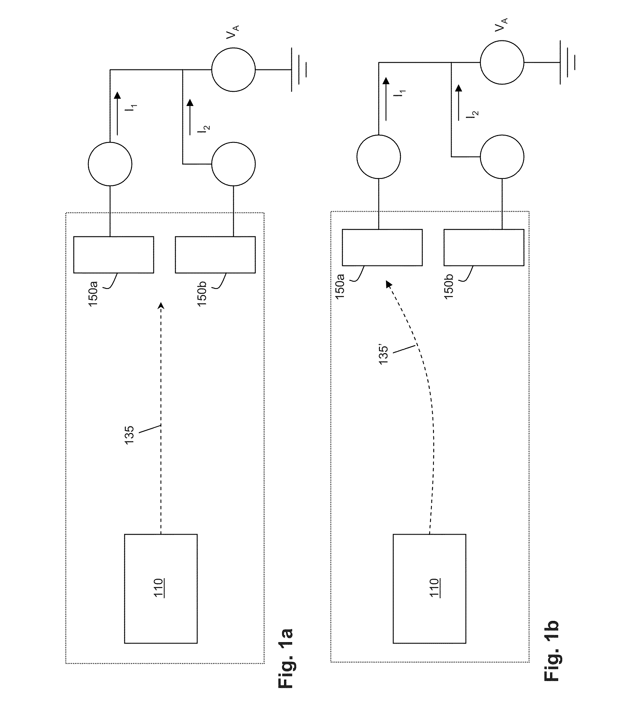
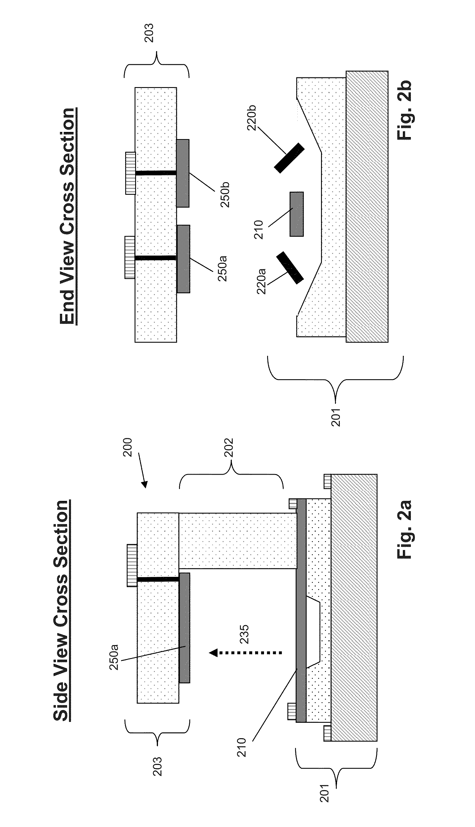
[0024]Exemplary electric-field sensors described herein comprise a novel micromachined approach to extremely small, sensitive, and low-power electric-field detection. Embodiments of the inventive electric-field sensor couple MEMS fabrication technologies with a unique system design ...


PUM


Abstract

Improved electric field (steered-electron electric-field, or SEEF) sensors and methods of manufacturing the same are provided. The SEEF sensors described herein may have increased sensitivity to low-frequency electric fields while being smaller than previously known sensors, and may allow for low-power electric field detection. The invention described herein allows for sensitive, long-term electric field monitoring for applications ranging from personnel detection to underground facility monitoring, as well as extraordinarily small vector sensing (full Poynting vector) for compact direction-finding of emitters of interest. Exemplary electric field sensors may accurately sense, measure, characterize and / or transmit electric field data over a wide frequency range. Importantly, such sensing, measuring, and / or characterizing do not require any physical or resistive contact between the sensor and a source of an electric field.

Description

CROSS-REFERENCE TO RELATED APPLICATIONS[0001]The present application claims benefit of similarly titled U.S. provisional patent application Ser. No. 61 / 484,505, filed on May 10, 2011, which is incorporated herein by reference in its entirety.GOVERNMENT RIGHTS STATEMENT[0002]Certain embodiments herein were made with government support under contract No. HR0011-10-C-0046, awarded by the Defense Advanced Research Project Agency (DARPA). The government has certain rights in those embodiments.FIELD OF THE INVENTION[0003]The invention relates to novel electric field sensors and methods of manufacturing the same.BACKGROUND[0004]Historically, sensitive, low-frequency electric-field sensors have been large devices, employing pairs of widely separated antennae or probes coupled to high-impedance voltmeters. The size of the antenna scales with the wavelength of the electromagnetic wave length and small sensors based on electro-optic materials are only sensitive at higher frequencies. More rece...

Claims


Application Information

Patent Timeline
Patent Type & Authority Patents(United States)
IPC IPC(8): G01R33/02G01R1/04G01R15/26
CPCG01R1/04G01R15/26G01R33/0213H01J23/09
Inventor WILLIAMS, KIRT REEDLIMB, SCOTTDE BRUYKER, DIRK
Owner PALO ALTO RES CENT INC
Learn More