
Machine vibration monitoring

a technology for monitoring machines and vibration signals, applied in the direction of machines/engines, liquid/fluent solid measurement, instruments, etc., to achieve the effect of quick and efficient analysis of vibration data

Active Publication Date: 2015-11-03
SIEMENS ENERGY INC
View PDF42 Cites 2 Cited by
  • Summary
  • Abstract
  • Description
  • Claims
  • Application Information

AI Technical Summary

Benefits of technology

[0003]It would be advantageous to enable a user to quickly and efficiently analyze vibration data which is filtered into its individual vectors. It would also be advantageous to then compare that filtered data real-time, or close thereto, with various operating conditions of the machine. Deviations from expected norms may then be identified and accounted for in heretofore unimaginable speed and precision.

Problems solved by technology

It is well known that rotating elements within machinery may subject the machinery to vibrations at different vectors related to operating frequency, yet most vibration monitors collect data as a composite for all vectors.

Method used


Image

  • Machine vibration monitoring
  • Machine vibration monitoring

Examples


Embodiment Construction

[0015]In describing the preferred embodiments of the subject matter illustrated and to be described with respect to the drawing, specific terminology will be resorted to for the sake of clarity. However, the invention is not intended to be limited to the specific terms so selected, and it is to be understood that each specific term includes all technical equivalents which operate in a similar manner to accomplish a similar purpose.

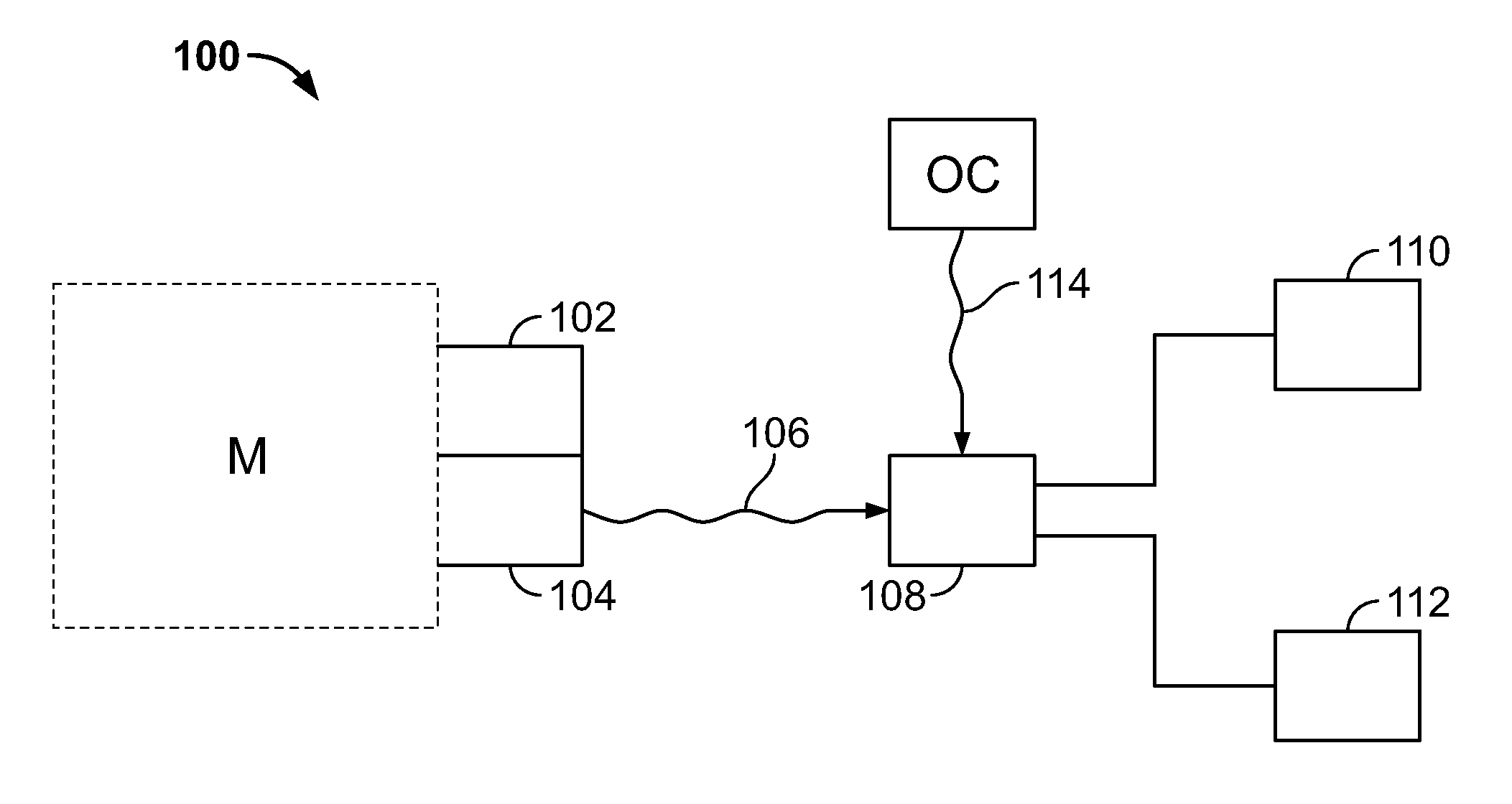
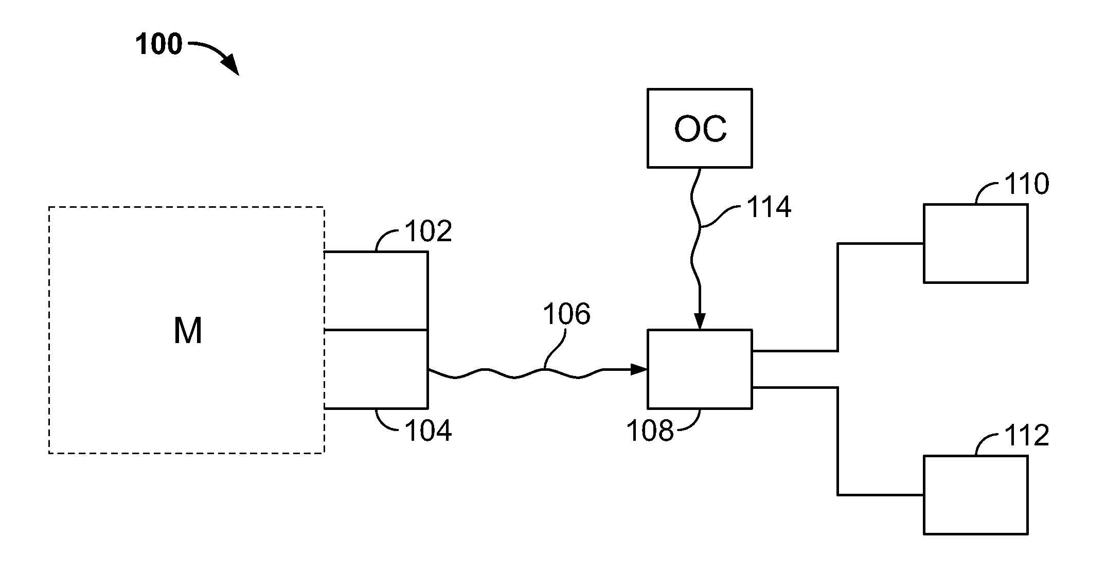
[0016]Described herein are embodiments of the vibration monitoring system and method of the present invention. In general, the invention is designed to obtain lateral vibration signals measured by accelerometers or proximiters, or torsional vibration signals measured by magnetic pickups or optical sensors, from a machine with rotating elements or a single rotating element. These vibration signals represent a combination of vectors, for example those at 1×, 2×, and 3× operating speed. The signals may then be filtered to obtain the individual vibration vecto...


PUM


Abstract

A system and method of monitoring vibrations, in a machine having a rotating element, where composite vibration signals are measured and filtered into discreet vector components associated with machine operating frequency. The filtered vectors are then evaluated to obtain a mean and standard deviation, whereupon a further value is obtained and compared to the prior values. Trip conditions may be set to initiate certain actions based on the meeting of the conditions. Additional data related to operating conditions of the machine may be analyzed in conjunction with the vibration data to be considered as providing a cause for vibration anomalies that may be observed. The operating, conditions of the machine may be displayed on a computer display in association with the discreet vector components, for example in a second level folder to the first level folder of the discreet vector components.

Description

CROSS REFERENCE TO RELATED APPLICATIONS[0001]This application claims the benefit of the filing date of U.S. Provisional Patent Application No. 61 / 347,990 filed May 25, 2010, the disclosure of which is hereby incorporated herein by reference.BACKGROUND OF THE INVENTION[0002]The present invention relates to the monitoring of vibration signals from machines with rotating elements. It is well known that rotating elements within machinery may subject the machinery to vibrations at different vectors related to operating frequency, yet most vibration monitors collect data as a composite for all vectors. As such, a single composite vibration vector is measured even though it results from a composite of, for example, 1× operating frequency, 2× operating frequency, and 3× operating frequency vibration vectors. Conventionally, this composite frequency vector is analyzed as such by hand in analyzation methods that are painstakingly slow. While this technique has been useful, it limits the abili...

Claims


Application Information

Patent Timeline
Patent Type & Authority Patents(United States)
IPC IPC(8): G08B21/00G01H1/00G01M13/02
CPCG01H1/003G01M13/028G01H1/00
Inventor SUN, YANXIACLAYTON, PETER J.SISMOUR, JR., ALBERT C.
Owner SIEMENS ENERGY INC
Learn More