Chain guide

a technology of chain guide and guide body, which is applied in the direction of belt/chain/gearring, mechanical equipment, belt/chain/gearring, etc., can solve the problems of increasing the cost the difficulty of compact design of the engine room e, and the inability to enlarge the guide body to the inner peripheral side, so as to reduce the installation space of the engine room, reduce the restriction, and increase the flexibility of designing devices

Active Publication Date: 2015-11-03
TSUBAKIMOTO CHAIN CO
View PDF35 Cites 0 Cited by
  • Summary
  • Abstract
  • Description
  • Claims
  • Application Information

AI Technical Summary

Benefits of technology

[0017]The present invention solves the above problems, and an object thereof is to provide the chain guide capable of improving the rigidity and the durability without enlarging its structure to the side opposite to the chain travel surface with a simple configuration and reducing the size of the guide shoe without increasing the number of components to thereby lower manufacturing cost.

Problems solved by technology

In the known chain guide described above, in order to secure the rigidity and durability of the chain guide, although it is necessary to increase the size of the guide body to improve the rigidity and durability thereof, since the known chain guide has almost all of the structure on the side opposite to the chain travel surface, in a case where the timing chain CH is guided from the outer peripheral side of the timing chain CH in the engine room E as shown in the example of FIG. 5, there has been a problem that it is not possible to enlarge the guide body to the inner peripheral side and a space needs to be secured on the outer peripheral side, which makes it difficult to design the engine room E compactly.
However, since it is necessary to use an expensive material optimum for sliding for the guide shoe, there has been a problem that its cost is increased.
However, there has been a problem that the number of components is increased and costs in assembly and maintenance are increased.

Method used


Image

  • Chain guide
  • Chain guide
  • Chain guide

Examples


first embodiment

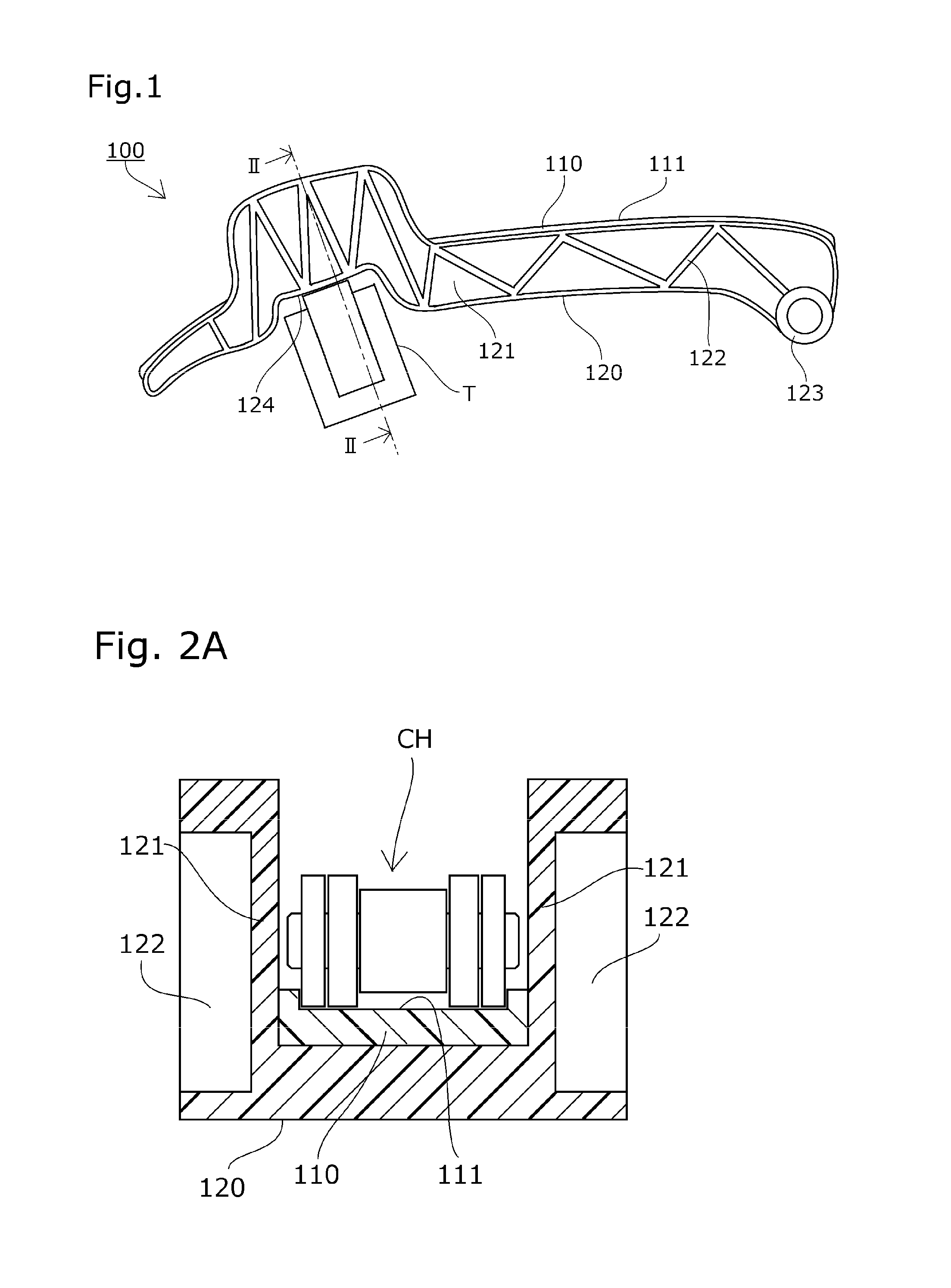
[0040]A description will be given of a chain guide (pivoting guide) 100 according to a first embodiment of the present invention based on the drawings.

[0041]The chain guide 100 according to the first embodiment of the present invention is pivotably supported in an engine having a timing system, guides and stabilizes the travel of a timing chain CH, is pressed to the side of the chain by a tensioner T to properly maintain tension and, as shown in FIGS. 1 and 2A, includes a guide shoe 110 and a guide body 120.

[0042]The guide body 120 has a pivoting boss portion 123 that is pivotably supported via support wall portions 121, and a pressed portion 124 that is pressed to the side of the chain by the tensioner T.

[0043]The support wall portions 121 are provided so as to be positioned at both sides of the guide shoe 110 in a width direction, and the support wall portions 121 are provided so as to extend to the side of the chain from the both sides of the guide shoe 110 in the width direction...

second embodiment

[0052]A description will be given of a chain guide (fixed guide) 200 according to a second embodiment of the present invention based on the drawings.

[0053]The chain guide 200 according to the second embodiment of the present invention is fixed in the engine having the timing system, guides and stabilizes the travel of the timing chain CH and, as shown in FIG. 3, includes a guide shoe 210 and a guide body 220.

[0054]The guide body 220 has fixed boss portions 225 that are provided at two positions and fixed in the engine via support wall portions 221.

[0055]The support wall portions 221 are provided so as to be positioned at both sides of the guide shoe 210 in the width direction. The support wall portions 221 are provided so as to extend to the side of the chain from the both sides of the guide shoe 210 in the width direction at the intermediate portion of the fixed boss portions 225 provided at two positions, and are provided so as to extend to the side opposite to the chain from the ...


PUM


Abstract

There is provided a chain guide capable of improving rigidity and durability without enlarging its structure to the side opposite to a chain travel surface with a simple configuration, and reducing the size of a guide shoe without increasing the number of components to thereby lower manufacturing cost. The chain guide includes the guide shoe and a guide body that supports the guide shoe, and the guide body has support wall portions that are provided near at least one side of both sides of the guide shoe in a width direction thereof so as to extend to the side of a chain at least at one position.

Description

BACKGROUND OF THE INVENTION[0001]1. Field of the Invention[0002]The present invention relates to a chain guide including a guide shoe that slidably guides a traveling chain and a guide body that supports the guide shoe along the direction of travel of the chain.[0003]2. Description of the Related Art[0004]Conventionally, a chain guide including a guide shoe that slidably guides a traveling chain is commonly used in order to stabilize the chain traveling between sprockets and properly maintain tension.[0005]For example, as shown in FIG. 5, there is known a timing system of an engine that causes a transmission chain CH such as a roller chain or the like endlessly wound between sprockets S1 and S2 provided at a crankshaft and a camshaft in an engine room E to travel in which the timing chain CH is endlessly wound between the driving sprocket S1 attached to the crankshaft in the engine room E and a pair of the driven sprockets S2 attached to the camshaft, and the timing chain CH is guid...

Claims


Application Information

Patent Timeline
Patent Type & Authority Patents(United States)
IPC IPC(8): F16H7/08F16H7/18
CPCF16H7/18F16H2007/0872F16H2007/185
Inventor MIYAZAWA, TOSHIHIKO
Owner TSUBAKIMOTO CHAIN CO
Why Eureka
Try Eureka