
Method and apparatus for programmable robotic rotary mill cutting of multiple nested tubulars

a rotary mill and robotic technology, applied in the direction of fluid removal, earthwork drilling and mining, borehole/well accessories, etc., can solve the problems of spiral cutting and failure of severance attempts, and achieve the effect of efficient severance installation

Inactive Publication Date: 2015-11-03
AES EOT EQUIP HLDG LLC
View PDF7 Cites 4 Cited by
  • Summary
  • Abstract
  • Description
  • Claims
  • Application Information

AI Technical Summary

Benefits of technology

The solution enables complete severance of tubulars and cement in a single trip, reducing time and environmental impact, providing visual verification and avoiding repeat trips due to cutter breakage, while efficiently handling non-concentric alignments.

Problems solved by technology

Traditional narrow-kerf abrasive waterjet systems often create a “spiral” cut because of an inability to maintain perfect alignment from the starting point to the ending point.
This “spiral” cut causes severance attempts to fail because the starting point of the cut and the ending point of the cut did not meet.

Method used


Image

  • Method and apparatus for programmable robotic rotary mill cutting of multiple nested tubulars
  • Method and apparatus for programmable robotic rotary mill cutting of multiple nested tubulars
  • Method and apparatus for programmable robotic rotary mill cutting of multiple nested tubulars

Examples


Embodiment Construction

[0036]Although described with reference to specific embodiments, one skilled in the art could apply the principles discussed herein to other areas and / or embodiments.

[0037]Throughout this disclosure casing(s) and tubular(s) are used interchangeably.

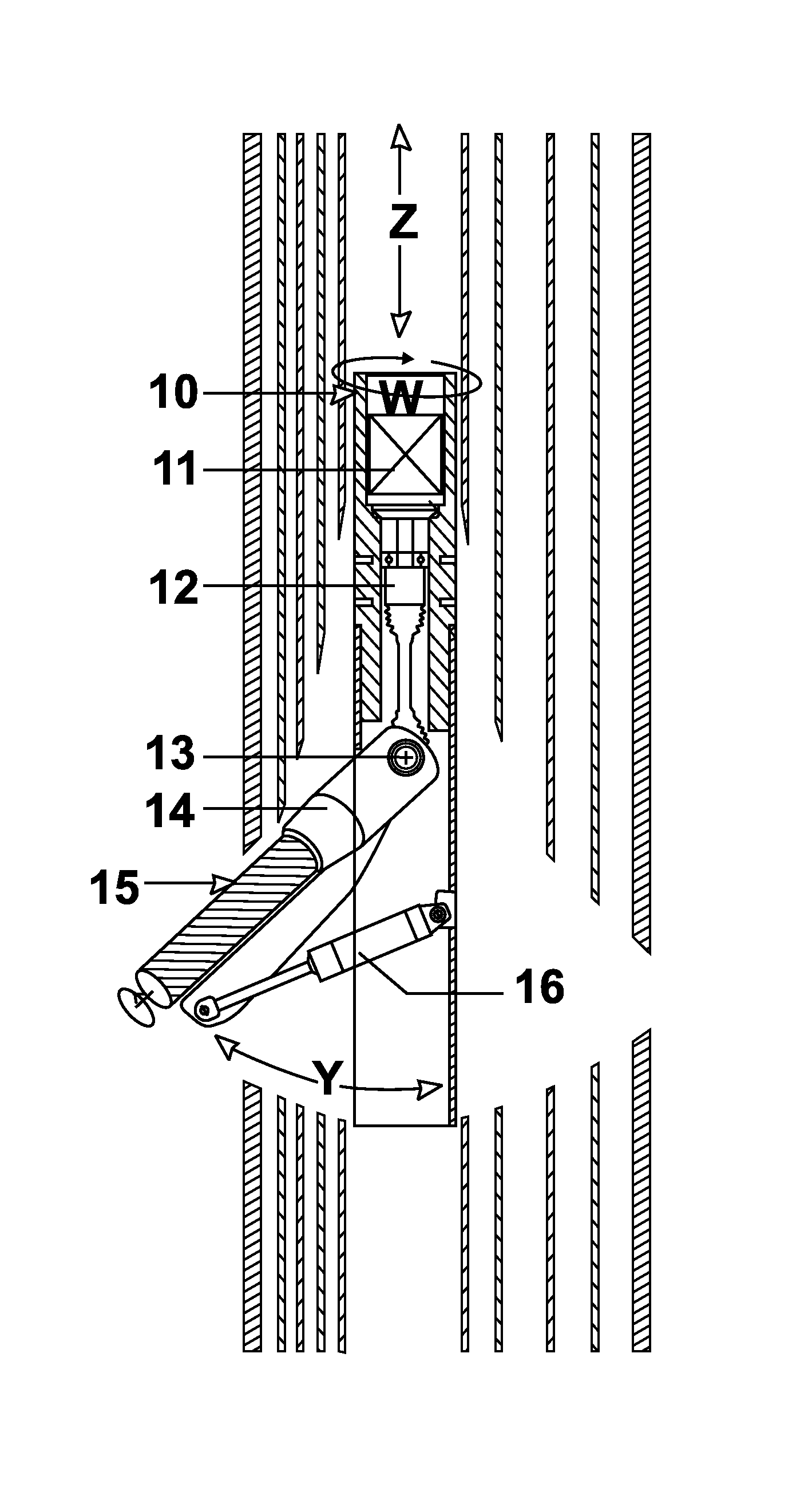
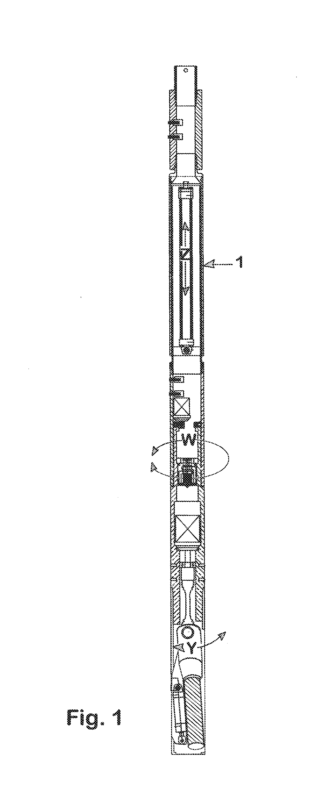
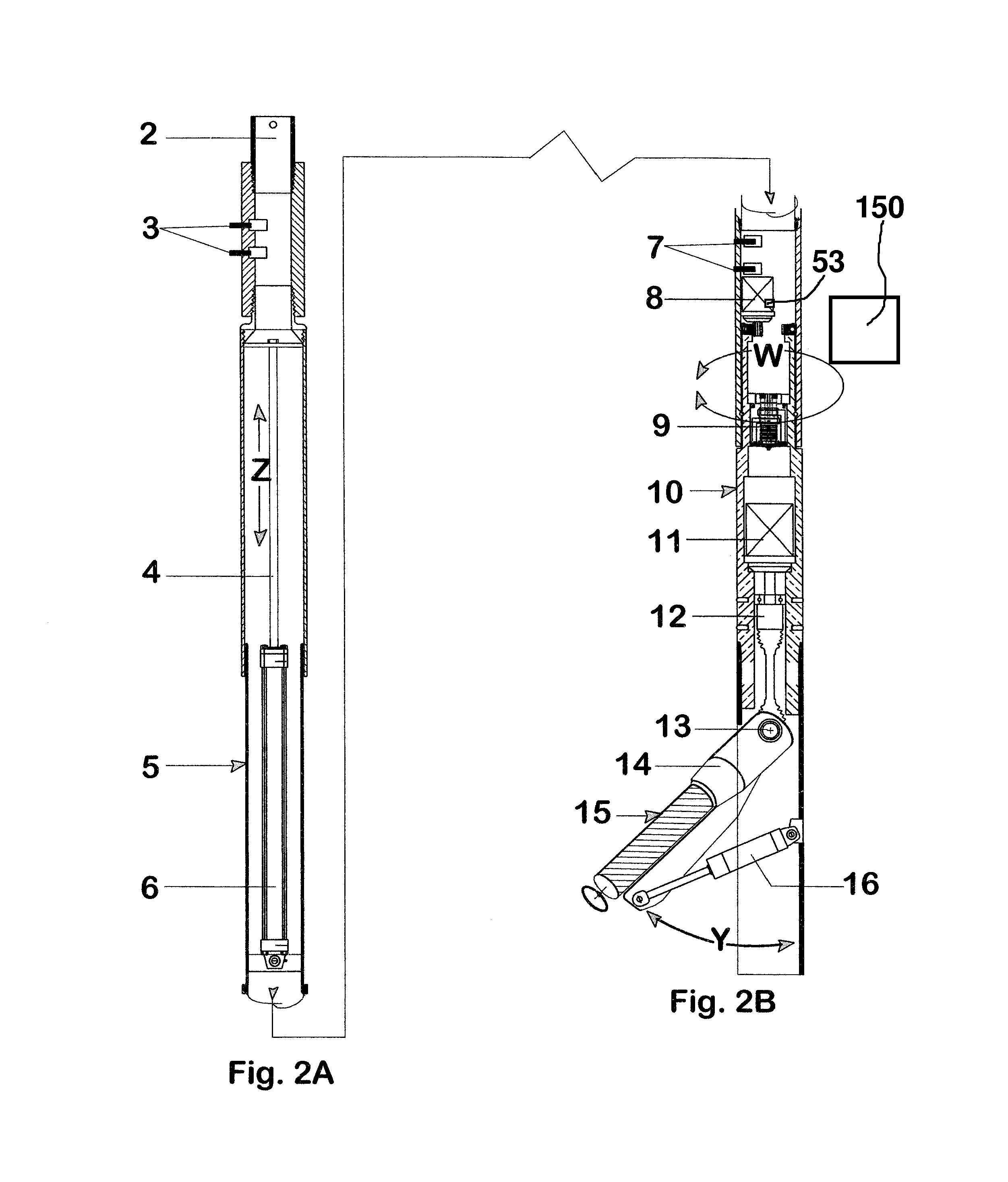
[0038]This invention provides a method and apparatus for efficiently severing installed tubing, pipe, casing, and liners, as well as cement or other encountered material in the annuli between the tubulars, in one trip into a well bore.

[0039]Reference will now be made in detail to the present embodiments of the disclosure, examples of which are illustrated in the accompanying drawings. Wherever possible, the same reference numbers will be used throughout the drawings to refer to the same or like parts (elements).

[0040]To help understand the advantages of this disclosure the accompanying drawings will be described with additional specificity and detail.

[0041]The method generally is comprised of the steps of positioning a robotic rotary mill...


PUM


Abstract

A methodology and apparatus for cutting shape(s) or profile(s) through well tubular(s), or for completely circumferentially severing through multiple tubulars, including all tubing, pipe, casing, liners, cement, other material encountered in tubular annuli. This rigless apparatus utilizes a computer-controlled, downhole robotic three-axis rotary mill to effectively generate a shape(s) or profile(s) through, or to completely sever in a 360 degree horizontal plane wells with multiple, nested strings of tubulars whether the tubulars are concentrically aligned or eccentrically aligned. This is useful for well abandonment and decommissioning where complete severance is necessitated and explosives are prohibited, or in situations requiring a precise window or other shape to be cut through a single tubular or plurality of tubulars.

Description

REFERENCE TO RELATED APPLICATION[0001]This application is a continuation-in-part of application Ser. No. 12 / 540,924, filed Aug. 13, 2009, entitled “Method and Apparatus for Programmable Robotic Rotary Mill Cutting of Multiple Nested Tubulars” which is a continuation-in-part of application Ser. No. 12 / 484,211, filed Jun. 14, 2009, entitled “Methodology and Apparatus for Programmable Robotic Rotary Mill Cutting of Multiple Nested Tubulars” which claims priority to application No. 61 / 131,874, filed Jun. 14, 2008, entitled “Rotary Milling Casing Cutter,” which is hereby fully incorporated by reference.FIELD OF THE INVENTION[0002]The present disclosure generally relates to methods and apparatus for mill cutting through wellbore tubulars, including casing or similar structures.BACKGROUND OF THE INVENTION[0003]When oil and gas wells are no longer commercially viable, they must be abandoned in accord with government regulations. Abandonment requires that the installed tubulars, including al...

Claims


Application Information

Patent Timeline
Patent Type & Authority Patents(United States)
IPC IPC(8): E21B29/00E21B44/00
CPCE21B29/005E21B44/00
Inventor MCAFEE, WESLEY MARKALLEY, MARK FRANKLIN
Owner AES EOT EQUIP HLDG LLC
Learn More