
Oral care instrument

a technology for oral cavity and nozzle, which is applied in the field of oral cavity instruments, can solve the problems of increasing the risk of being contaminated from the distal end of the nozzle, the difficulty of ejecting the solution, and the amount of remaining drug after use, so as to prevent an excess amount of oral composition, improve the insertability of details in the oral cavity, and reduce the effect of ejection

Active Publication Date: 2015-11-03
SUNSTAR INC
View PDF10 Cites 7 Cited by
  • Summary
  • Abstract
  • Description
  • Claims
  • Application Information

AI Technical Summary

Benefits of technology

[0023]In the oral care instrument according to the present invention configured as described above, the supply path for supplying the oral composition from the handle body to the nozzle portion of the head body through the inner side of the neck body is provided and the head body is detachably coupled to the neck body. This makes it possible to wash and dry the nozzle portion at the distal end or the like by detaching the head body after used so that the good oral care instrument in terms of a hygiene viewpoint is obtained.
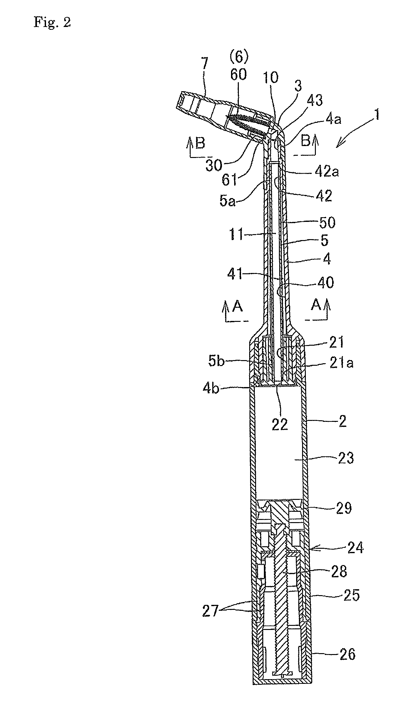
[0024]In the oral care instrument, a plurality of ribs which are projected in the direction of a center axis, and are extended long in the axial direction are provided on the inner circumferential wall of the neck body. A cylindrical tube member which has an inner diameter of 1 to 2 mm and constitutes the supply path of the oral composition is inserted and attached to the neck body in such a manner that the outer circumferential face of the tube member is supported by the plurality of ribs. Accordingly, even if the outer diameter or thickness of the neck body is made smaller, a sufficient strength can be obtained and the insertability to details in the oral cavity can be improved. Further, the supply path can be made to have a required minimum size of a cross-sectional area by setting a size of the tube member, thereby preventing an excess amount of the oral composition from being supplied.
[0025]In other words, since the neck body is required to have strength enough to support forces received from the head body in use, the neck body is required to have a certain size in diameter. Further, if the thickness of the neck body is decreased in consideration of the material cost, an internal space thereof is made larger. Conventionally, it is believed that the oral composition can be flown through the internal space itself as a supply path. However, if the supply path is wide beyond necessity, there arise a problem that the drug solution is hard to be ejected at the start of use, and a problem that the amount of remaining drug after use is large and the risk of being contaminated from the distal end of the nozzle is increased. On the other hand, if the supply path is made smaller at the time of forming the supply path, the strength and durability of a produced mold is made worse, and the following problem is caused at the same time. The problem is that the oral composition pushed out to the supply path does not stop immediately even when the pushing operation is stopped and an excess amount of the oral composition are ejected and wasted, although depending on rheological characterization of the oral composition. In order to solve the problems, a plurality of ribs are projected to the inner circumferential face and a tube member is provided at an inner side of the ribs to make a supply path in the invention. With the ribs provided, even if the outer diameter and thickness of the neck body are made smaller, a sufficient strength can be obtained. At the same time, since the oral composition is supplied through the tube member at the inner side of the ribs, a cross-sectional area of the tube member can be appropriately set in accordance with the rheological characterization of the oral composition, thereby preventing an excess amount of the oral composition from being supplied.
[0026]Even in a case where the neck body is injection-molded by a synthetic resin, since a convex and concave configuration for forming ribs is provided on a mold forming an internal space, durability and strength of the mold can be maintained so that the neck body having small outer diameter and thickness can be formed at high accuracy. Further, an operation in which the tube member separately formed is mounted in the neck body can be easily performed without fail, and an assembling operation can be easy. That is because when the tube member is inserted to be attached, the tube member is supported and guided by the above ribs so that the tube member can be located at a center position at which an axis of the tube member matches to that of the neck portion by simply pushing the tube member, and the contact area causing a resistance when inserted is small.
[0027]Moreover, an application member formed of a bundle of filaments is provided at the nozzle portion of the head body. This makes it possible to apply the oral composition to or into detailed sites in the oral cavity. Therefore, the oral composition can be also applied after the contaminants are cleaned with a bundle of filaments.
[0028]In addition, since the application member is formed of only one bundle of filaments, the application member can be easily produced and an operation of applying the oral composition to or into detailed sites in the oral cavity when used is effectively performed.

Problems solved by technology

If the internal space is made larger as described above, there arise a problem that the drug solution is hard to be ejected at the start of use, and a problem that the amount of remaining drug after use is large and the risk of being contaminated from the distal end of the nozzle is increased.
On the other hand, if the internal space is made too small, durability of a produced mold is made worse, and the following problem is caused.
The problem is that when the gel or cream oral composition flows through the internal space of the washing solution discharge tube as a supply path, the oral composition transmitted to the supply path does not stop immediately even when the transmitting operation is stopped and thus an excess amount of the oral composition are ejected and wasted.

Method used


Image

  • Oral care instrument
  • Oral care instrument
  • Oral care instrument

Examples


Embodiment Construction

[0062]Hereinafter, an embodiment of the present invention is described in detail with reference to the accompanying drawings.

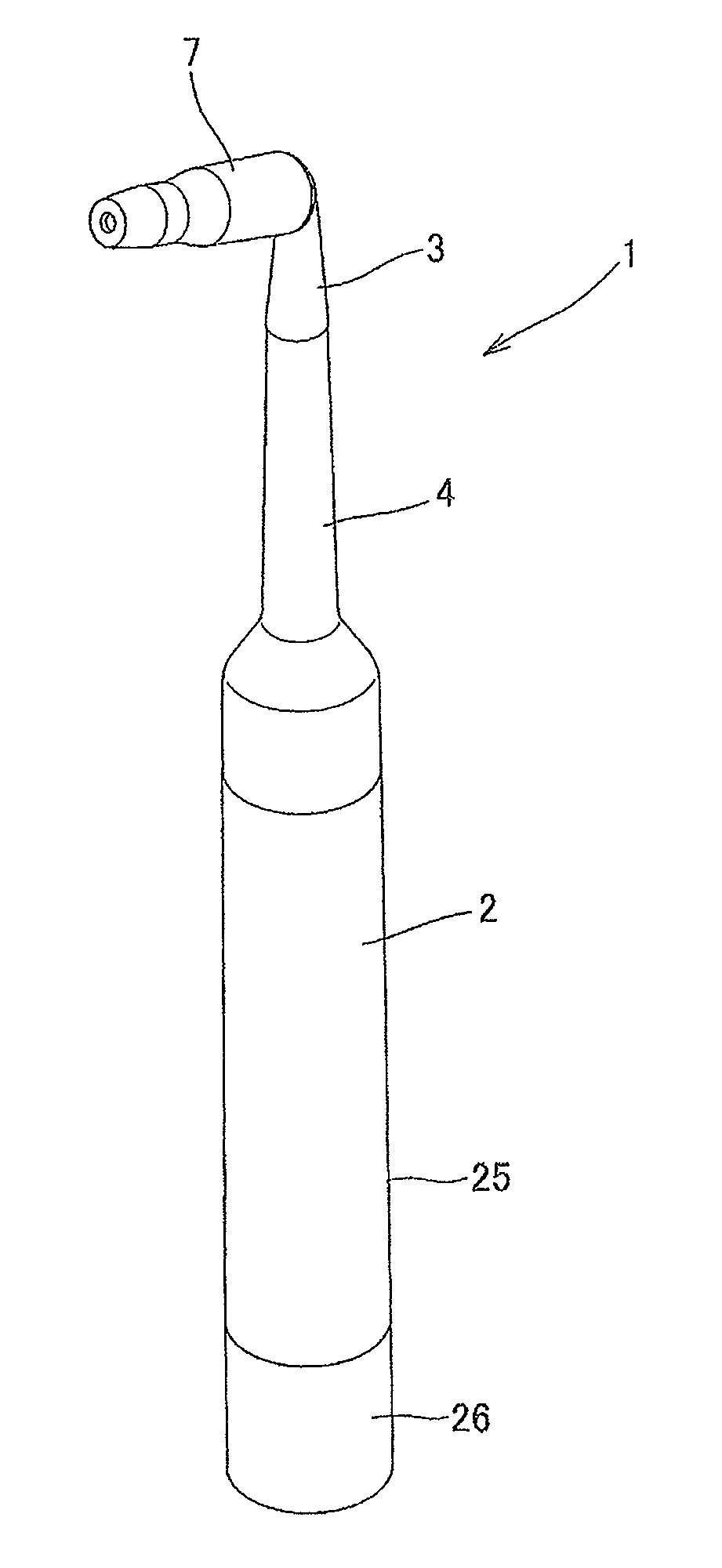
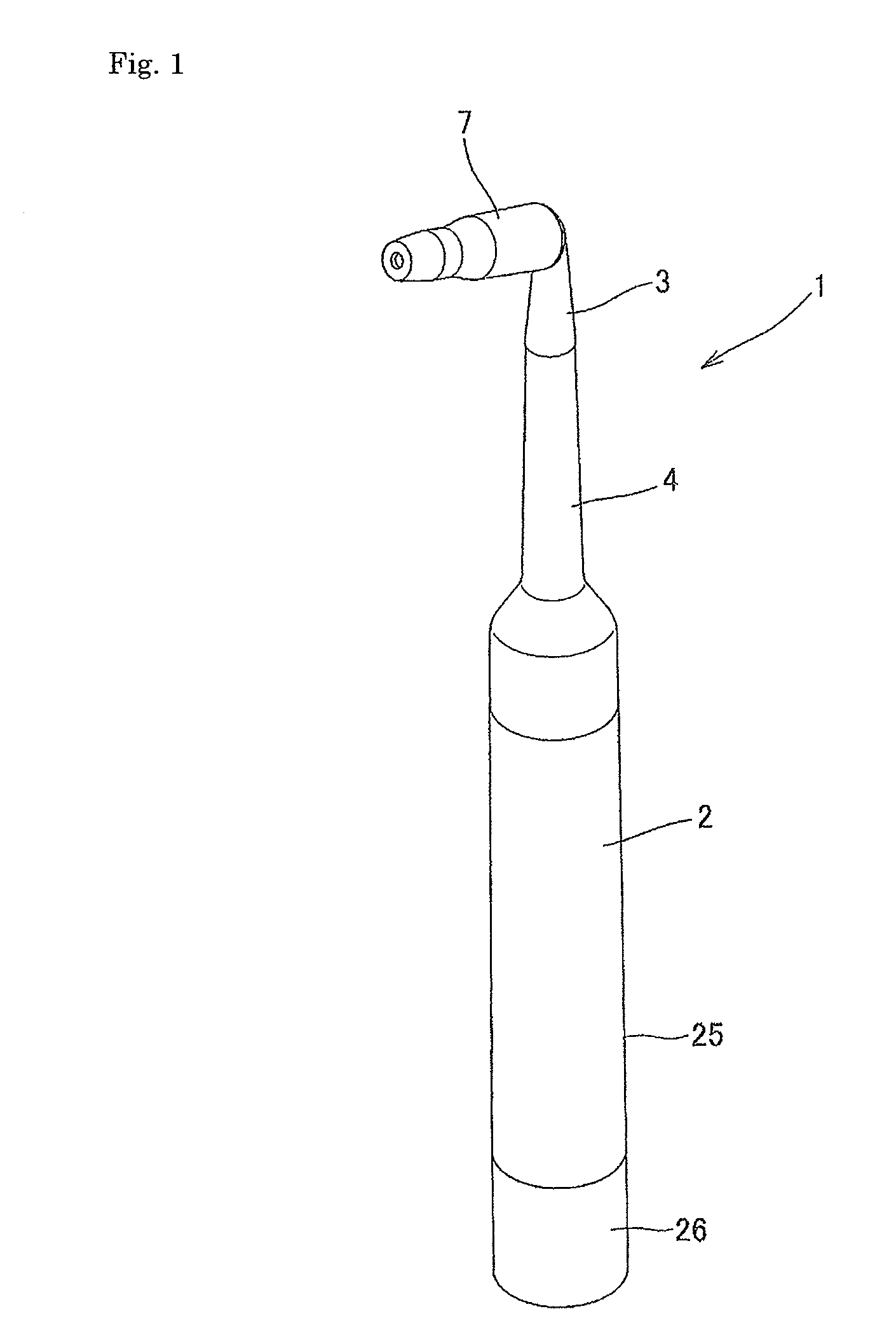
[0063]FIG. 1 is a perspective view illustrating an overall configuration of an oral care instrument according to the invention, and FIG. 2 is a longitudinal cross-sectional view in which a distal end side from a handle body 2 is fractured partially. FIGS. 1 to 8 show a representative embodiment of the invention. In the drawings, reference numeral 1 indicates the oral care instrument, 2 indicates the handle body, 3 indicates a head body, and 4 indicates a neck body.

[0064]As shown in FIGS. 1 and 2, the oral care instrument 1 is an instrument for applying a gel or cream oral composition in an oral cavity by discharging the oral composition from a nozzle portion 10 at a distal end of the oral care instrument 1. The oral care instrument 1 includes the handle body 2 gripped by a user when used, the head body 3 having the nozzle portion 10 for discharging the oral co...


PUM

PropertyMeasurementUnit
inner diameteraaaaaaaaaa

Abstract

An oral care instrument, which can maintain a sufficient support strength of a long neck, leaves little residue of a medicant after using, has a low contamination risk from nozzle tip, allows smooth spouting of a medical solution from the beginning, prevents excessive supply of gelatinous or creamy oral-care composition in the case of flowing the composition in a supply channel inside the same, and contributes to the maintenance of the durability of a manufacturing mold. In the aforesaid oral care instrument, which comprises a handle (2), a head (3) and a neck (4), a channel (11) for supplying oral-care composition running within the neck (4) to a nozzle (10) of the head (3) via the handle (2), is formed; and the head (3) is connected in a detachable manner to the neck (4).

Description

TECHNICAL FIELD[0001]The present invention relates to an oral care instrument for applying an oral composition in an oral cavity by discharging the oral composition from a nozzle portion at a distal end of the oral care instrument.BACKGROUND ART[0002]As an oral care instrument of this type, there is conventionally proposed an oral care instrument which includes washing solution supply means, and a long washing solution discharge tube attached to the washing solution supply means (for example, see Japanese Unexamined Patent Publication No. 2007-167088). In this oral care instrument disclosed in Japanese Unexamined Patent Publication No. 2007-167088, an elastic nozzle is provided at a distal end of the washing solution discharge tube, and the washing solution supply means is composed of a washing solution container having a pumping function. In addition, every time a pressing portion (button) provided on the washing solution container is pressed, the washing solution is ejected from a...

Claims


Application Information

Patent Timeline
Patent Type & Authority Patents(United States)
IPC IPC(8): A46B11/00A46B5/00A46B7/04A61C5/06A61C19/06
CPCA46B11/0027A46B5/0095A46B7/04A46B11/0086A46B11/0089A46B2200/108A61C5/062A61C19/063A61C3/005A46B3/06A46B3/10A61C5/62
Inventor TSURUKAWA, NAOKITOKUOKA, SEIJIHAMADA, MASAFUMISUMIYOSHI, SATORU
Owner SUNSTAR INC
Learn More